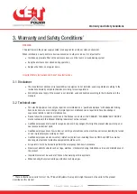
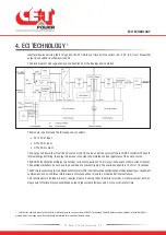


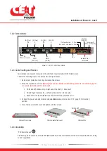


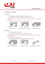


7.2.2 Terminations
PE
GND
Inview S Slot
GND
Chassis Ground
(AC IN)
Terminals
(AC Out)
DC -
DC +
6 Pin
8 Pin
(To Parallel the
Bravo 10 - shelves)
ON/OFF
Remote
(CE+T COM port)
To Inview S
(AC Out)
N
(AC IN)
N
(AC Out)
L
(AC IN)
L
Bravo 10 - 48/230 - Shelf Rear Details
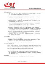
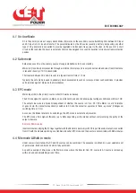
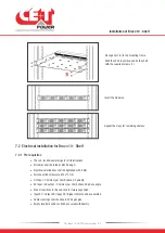
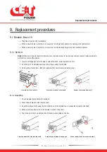
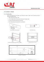
7.2.3 Cable Routing and Fixation
Terminations are present at rear side of the shelf and it is protected with IP 20 metal cover.
Perform the following steps to connect power and signal cables:
1. Remove rear protection cover by unscrewing two screws.
2. Break the required knock outs.
(Warning: Take special attention while breaking knockouts to avoid damaging the
connectors, terminals and PCB in the shelf.)
AC IN and OUT cables entry – Right end of the shelf (1 - Knock out)
DC and Signal cables entry – Left end of the shelf (2 - Knock outs)
Knock outs are also available at top and bottom of the protection cover.
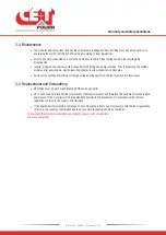
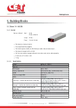
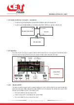
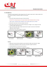
3. Connect the power and signal cables with
supplied screws,
refer section 7.2.2, page 20 for terminals
position.
4. Close the rear protection cover and tighten with two screws.
Screw
Screw
Remove two screws
Remove protection cover
Cable entries
DC
Signal
AC IN & OUT
AC IN
DC -
DC +
AC Out
Signal
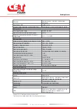
7.2.4 Grounding
“PE Chassis Ground”
PE Chassis ground should be wired to MET (Main Earth Terminal) or distributed earth bar connected to MET, according
to local regulations.
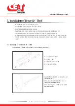
Installation of Bravo 10 - Shelf
20
- Bravo 10 - 48/230 - User manual - v1.2
Содержание Bravo 10 - 48/230
Страница 43: ......


