


ECI TECHNOLOGY
10
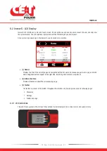
- Bravo 10 - 48/230 - User manual - v1.2
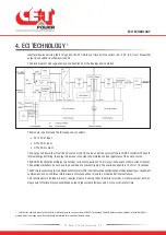
4. ECI TECHNOLOGY
1
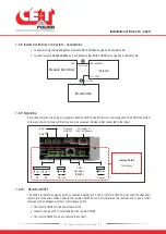
Inverter modules carrying the ECI logo and the EPC mark are triple port converters (AC in, DC in, AC out). Sinusoidal
output is converted from Mains or/and DC.
The block diagram below gives an explicit description of the topology and operation.
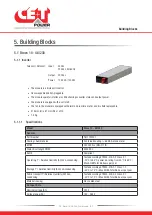
The module is built around the following sub-converters
•
AC to DC at input
•
DC to DC at input
•
DC to AC at output
The energy can flow either from the AC source or the DC source under the control of the local DSP controller. Thanks to
internal energy buffering, the output sine wave is constant and disturbance free regardless of the active source.
The BOOST functionality multiples the nominal current for a period of 20 ms (max) in the event of down stream failures.
The upstream breakers do not have to be oversized to prevent tripping. The overload capacity is 150% for 15 seconds.
The ECI works according to True Redundant Structure (TRS) that features decentralized and independent logic, redundant
communication bus and three internal levels of disconnection to isolate a module after internal failure.
This functionality is included in every inverter module. Running them in parallel provides a modular system with, no
single point of failure, always-conditioned output, high system efficiency and 0 ms source transfer time.
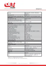
1 Information and data given in this chapter is intended to serve as an overview of the ECI Technology. Detailed features and parameters for each individual
module type in the range may differ and should be referred to in the dedicated data sheet.
Содержание Bravo 10 - 48/230
Страница 43: ......


