


Reference Manual V1.10
Software Versions 3.xx
Page 26
X300-621-110
7.
Calibration
The calibration of the indicator is fully digital. The calibration results are stored in permanent memory
for use each time the instrument is powered up.
Note: Some of the digital setup steps can affect calibration. The BUILD and OPTION settings
MUST be configured before calibration is attempted.
To perform a calibration, when in Full Setup select the
CAL
Group using the
<GRP>
key.
The calibration programme will automatically prevent the instrument from being calibrated into an
application outside of its specification. If an attempt is made to calibrate outside of the permitted
range, an error message will display and the calibration will be abandoned. Refer to Error Messages
page 53.
The instrument has a wide-range A/D converter. The industrial calibration range of the instrument
extends well beyond the Trade approved range.
Note: It should not be assumed that just because the instrument has successfully calibrated
a scale, that the scale is correct for trade use. Always check the scale build against the
approval specification.
7.1.
Performing a Digital Calibration with Test Weights
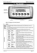
Figure 16: Chart - Zero and Span Points to Interpolate Weight from Load Cell
The Zero setting (CAL:ZERO) specifies a gross zero point for the scale. The Span setting
(CAL:SPAN) specifies a second point
(preferably close to full scale)
used to convert the
A/D readings into weighing units (eg. kg). Select either of the Zero (CAL:ZERO) or Span
(CAL:SPAN) calibration items. It is important that an initial Zero calibration is performed
before any SPAN calibrations. The chart shown here demonstrates how the zero and span
points are used to interpolate a weight reading from the load cell reading.
Note: Calibration points (Zero and Span) must be spaced by at least 2% of Full scale
from each other.
0
500
1000
1500
2000
2500
3000
3500
0
2
4
6
8
10
W
e
ight
(K
g)
Load Cell Output (mV)
Span Point
(preferably at full load)
Zero Point