


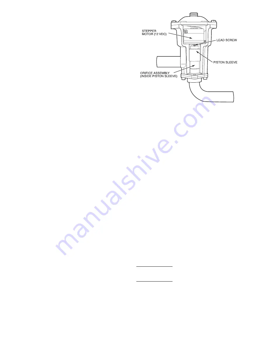
Electronic Expansion Valve (EXV) (See Fig. 14)
—
Standard units are equipped with a bottom seal EXV. This
device eliminates the use of the liquid line solenoid pump-
down at unit shutdown. An O-ring has been added to bottom
of orifice assembly to complete a seal in the valve on shut-
down. This is not a mechanical shut-off. When service is re-
quired, use the liquid line service valve to pump down the
system.
High pressure refrigerant enters bottom of valve where it
passes through a group of machined slots in side of orifice
assembly. As refrigerant passes through the orifice, it drops
in pressure. To control flow of refrigerant, the sleeve slides
up and down along orifice assembly, modulating the size of
orifice. The sleeve is moved by a linear stepper motor that
moves in increments controlled directly by the processor. As
stepper motor rotates, the motion is translated into linear move-
ment of lead screw. There are 1500 discrete steps with this
combination. The valve orifice begins to be exposed at
320 steps. Since there is not a tight seal with the orifice and
the sleeve, the minimum position for operation is 120 steps.
Two thermistors are used to determine suction superheat.
One thermistor is located in the cooler and the other is lo-
cated in the cylinder end of the compressor after refrigerant
has passed over the motor. The difference between the
2 thermistors is the suction superheat. These machines are
set up to provide approximately 5 to 7 F (2.8 to 3.9 C) super-
heat leaving the cooler. Motor cooling accounts for approxi-
mately 22 F (12.2 C), resulting in a superheat entering com-
pressor cylinders of approximately 30 F (16.7 C). This increases
performance of cooler by reducing the amount of superheat
needed.
Because the valves are controlled by the EXV module, it
is possible to track the position of the valve. Valve position
can be used to control head pressure and system refrigerant
charge.
During initial start-up, the EXV module will drive each
valve fully closed. After initialization period, valve position
is controlled by the EXV module and the MBB.
The EXV is used to limit the maximum cooler saturated
suction temperature to 55 F (12.8 C). This makes it possible
for the chiller to start at high cooler fluid temperatures with-
out overloading the compressor.
Energy Management Module (Fig. 15) —
This
factory-installed option or field-installed accessory is used
for the following types of temperature reset, demand limit,
and/or ice features:
• 4 to 20 mA leaving fluid temperature reset (requires field-
supplied 4 to 20 mA generator)
• 4 to 20 mA cooling set point reset (requires field-supplied
4 to 20 mA generator)
• Discrete inputs for 2-step demand limit (requires field-
supplied dry contacts capable of handling a 5 vdc, 1 to
20 mA load)
• 4 to 20 mA demand limit (requires field-supplied 4 to 20
mA generator)
• Discrete input for Ice Done switch (requires field-supplied
dry contacts capable of handling a 5 vdc, 1 to 20 mA load)
See Demand Limit and Temperature Reset sections on
pages 43 and 45 for further details.
Capacity Control —
The control system cycles com-
pressors, unloaders, and hot gas bypass solenoids to main-
tain the user-configured leaving chilled fluid temperature set
point. Entering fluid temperature is used by the Main Base
Board (MBB) to determine the temperature drop across the
cooler and is used in determining the optimum time to add
or subtract capacity stages. The chilled fluid temperature set
point can be automatically reset by the return temperature
reset or space and outdoor-air temperature reset features. It
can also be reset from an external 4 to 20 mA signal (re-
quires Energy Management Module FIOP/accessory).
With the automatic lead-lag feature in the unit, the control
determines randomly which circuit will start first, A or B. At
the first call for cooling, the lead compressor crankcase heater
will be deenergized, a condenser fan will start, and the com-
pressor will start unloaded.
NOTE: The automatic lead-lag feature is only operative when
an even number of unloaders is present. The 040-070 units
require an accessory unloader for the lead-lag feature to be
in effect.
If the circuit has been off for 15 minutes, and the unit is
a TXV unit, liquid line solenoid will remain closed during
start-up of each circuit for 15 seconds while the cooler and
suction lines are purged of any liquid refrigerant. For units
with EXVs, the lead compressor will be signaled to start.
The EXV will remain at minimum position for 10 seconds
before it is allowed to modulate.
After the purge period, the EXV will begin to meter the
refrigerant, or the liquid line solenoid will open allowing the
TXV to meter the refrigerant to the cooler. If the off-time is
less than 15 minutes, the EXV will be opened as soon as the
compressor starts.
The EXVs will open gradually to provide a controlled start-up
to prevent liquid flood-back to the compressor. During start-
up, the oil pressure switch is bypassed for 2 minutes to al-
low for the transient changes during start-up. As additional
stages of compression are required, the processor control will
add them. See Tables 5A and 5B.
If a circuit is to be stopped, the control will first start to
close the EXV or close the liquid line solenoid valve.
For units with TXVs, the lag compressor(s) will be shut down
and the lead compressor will continue to operate for 10 sec-
onds to purge the cooler of any refrigerant.
For units with EXVs, the lag compressor(s) will be shut down
and the lead compressor will continue to run. After the lag
compressor(s) has shut down, the EXV is signaled to close.
The lead compressor will remain on for 10 seconds after the
EXV is closed.
During both algorithms (TXV and EXV), all diagnostic
conditions will be honored. If a safety trip or alarm condi-
tion is detected before pumpdown is complete, the circuit
will be shut down.
Fig. 14 — Electronic Expansion Valve (EXV)
16
Содержание 30GTN
Страница 6: ...Fig 1 Typical Control Box 080 110 and Associated Modular Units Shown 6 ...
Страница 7: ...Fig 2 24 V Control Schematic Unit Sizes 040 070 7 ...
Страница 8: ...Fig 3 24 V Control Schematic Unit Sizes 080 110 230B 315B 8 ...
Страница 9: ...Fig 4 24 V Control Schematic Unit Sizes 130 210 230A 315A 330A B 420A B 9 ...
Страница 75: ......