62-10848
5-10
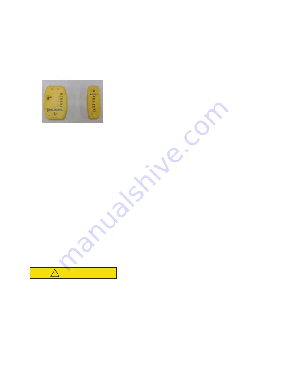
5.16 Diagnostic Tool
NOTE
The Cab Command diagnostic tool comes
with two jumpers. These are not applicable
to the 30S system and should not be used in
this application.
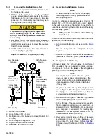
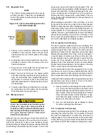
Figure 5.10 Cab Command Diagnostic Tool
(CTD P/N 07-00440-00)
a. Testing a cab command cable that is already
installed on the unit and routed into the truck
cab requires the use of both pieces of the diag-
nostic tool.
b. Unplug the cab command cable from the micro-
processor and also from the back of the cab
command module.
c. Plug one end of the cable into the primary tool
and the other end into the remote tool.
d. Begin the test by turning on the power switch
and observing the sequence of green lights. As
each circuit is tested, the corresponding light is
illuminated. If a fault is found in the cable, the
light that corresponds to that particular circuit is
not illuminated.
e. To test a cable that is not installed on a unit, sim-
ply plug each end of the cable into the primary
tool and perform the test as above.
5.17 Microprocessor
CAUTION
!
Under no circumstances should anyone
attempt to repair the microprocessor
module or Cab Command! Should a prob-
lem develop with these components, con-
tact your nearest Carrier Transicold
dealer for replacement.
Although there is less danger of electrical static dis-
charge (ESD) damage in the outdoor environment,
where the processor is likely to be handled, proper
board handling techniques should be stressed. Boards
should always be handled by their edges, in much the
same way one would handle a photograph. This not
only precludes the possibility of ESD damage, but also
lowers the possibility of physical damage to the elec-
tronic components. Although the microprocessor
boards are fairly rugged when assembled, they are
more fragile when separated and should always be
handled carefully.
When welding is required on the unit frame, or on the
front area of the truck, ALL wiring to the microprocessor
MUST be disconnected. When welding is performed on
other areas of the truck and van, the welder ground con-
nection MUST be in close proximity to the area being
welded. It is also a good practice to remove both battery
cables before welding on either the unit frame or the
truck to prevent possible damage to other components
such as the alternator and voltage regulator.
5.18 Evaporator Coil Cleaning
The use of recycled cardboard cartons is increasing. The
recycled cardboard cartons create much more fiber dust
during transport than “new” cartons. The fiber dust and
particles are drawn into the evaporator where they lodge
between the evaporator fins. If the coil is not cleaned on
a regular basis, sometimes as often as after each trip,
the accumulation can be great enough to restrict air flow,
cause coil icing, repetitive defrosts and loss of unit
capacity. Due to the ”washing” action of normal defrost
the fiber dust and particles may not be visible on the face
of the coil but may accumulate deep within.
It is recommended to clean the evaporator coil on a reg-
ular basis, not only to remove cardboard dust, but to
remove any grease oil film which sometimes coats the
fins and prevents water from draining into the drain pan.
Cardboard fiber particles after being wetted and dried
several times can be very hard to remove. Therefore,
several washings may be necessary.
a. Spray coil with a mild detergent solution such as
any good commercial-grade automatic dish
washer detergent and let the solution stand for a
few minutes. Reverse flush (opposite normal air
flow) with clean water at mild pressure. A gar-
den hose with spray nozzle is usually sufficient.
Make sure drain lines are clean.
b. Run unit until defrost mode is initiated to check
for proper draining from drain pan.
5.19 Condenser Coil Cleaning
Remove all foreign material from the condenser coil by
reversing the normal air flow. (Air is pulled in through
the front.) Compressed air or water may be used as a
cleaning agent. It may be necessary to use warm water
mixed with any good commercial dishwasher deter-
gent. Rinse coil with fresh water if a detergent is used.
P
rimary
Tool
Remote
Tool
Содержание INTEGRA 30S
Страница 2: ......
Страница 4: ......
Страница 8: ......
Страница 14: ...62 11868 1 8 ...
Страница 18: ......
Страница 32: ......
Страница 40: ......
Страница 60: ......
Страница 62: ......
Страница 64: ......
Страница 65: ...62 10848 Figure 7 2 Electrical Schematic Wiring Diagram Based On Dwg No 62 61350 Rev E ROAD ONLY ...
Страница 66: ......
Страница 69: ......


