62-10848
2-4
2.3.9
High Pressure Switch (HP1)
HP1 is a normally closed switch which monitors the
system for high pressure and shuts down the unit when
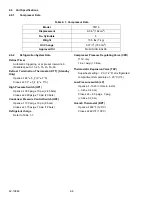
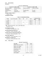
pressure rises above a predetermined setting. For HP1
2.3.10
Condenser Pressure Control Switch (HP2)
HP2 is a normally open switch which closes to signal
the microprocessor to activate the condenser fan. HP2
also cycles the condenser pressure control valve
(HGS2) and the quench valve (BPV) in addition to the
condenser fan in order to maintain head pressure for
heating capacity. For HP2 settings see
.
2.4
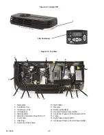
Evaporator Section
The evaporator assembly consists of an evaporator
fan, evaporator coil, thermostatic expansion valve,
defrost termination thermostat, a compressor pressure
regulating valve (115V only) and a quench valve.
2.4.1
Thermostatic Expansion Valve
The thermostatic expansion valve is an automatic
device which controls the flow of liquid to the evapora-
tor according to changes in superheat to the refrigerant
leaving the evaporator. The thermal expansion valve
maintains a relatively constant degree of superheat in
the gas leaving the evaporator regardless of suction
pressure. Thus, the valve has a dual function; auto-
matic expansion control and preventing liquid from
returning to the compressor. For TXV superheat set-
tings see
. To adjust the TXV, refer to
2.4.2
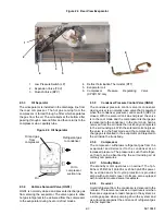
Compressor Pressure Regulating Valve
(CPR) (115V Only)
(See
The CPR valve is installed on the suction line of the
standby compressor to regulate the suction pressure
entering the compressor. The CPR valve is set to limit
the maximum suction pressure. For CPR settings refer
The suction pressure is controlled to avoid overloading
the electric motor during high refrigerated compartment
temperature operation. To adjust the CPR valve, refer
2.4.3
Defrost Termination Thermostat (DTT)
This normally closed thermal switch is on Standby units
only. As the evaporator cools to set point, the switch
closes and signals microprocessor that defrost may be
initiated. Switch terminates defrost by opening at pre-
determined set point. For DTT settings refer to
2.4.4
Quench Valve (BPV)
The quench valve is a normally closed solenoid valve
controlled by the quench thermostat (BPT) mounted on
the road compressor discharge line. The valve allows
metered liquid refrigerant to enter the suction line in the
evaporator in order to provide compressor cooling. For
BPT settings refer to
2.4.5
Evaporator
The evaporator is of the tube and fin type. The opera-
tion of the compressor maintains a reduced pressure
within the coil. At this reduced pressure, the liquid
refrigerant evaporates at a temperature sufficiently low
enough to absorb heat from the air. Air movement over
the evaporator is provided by an electric fan.
2.4.6
Low Pressure Switch (LP)
The low pressure switch is a normally closed switch
which signals the microprocessor to shut down the unit
when the system is outside of the low pressure limit.
For LP settings refer to
Содержание INTEGRA 30S
Страница 2: ......
Страница 4: ......
Страница 8: ......
Страница 14: ...62 11868 1 8 ...
Страница 18: ......
Страница 32: ......
Страница 40: ......
Страница 60: ......
Страница 62: ......
Страница 64: ......
Страница 65: ...62 10848 Figure 7 2 Electrical Schematic Wiring Diagram Based On Dwg No 62 61350 Rev E ROAD ONLY ...
Страница 66: ......
Страница 69: ......


