5-3
62-10848
5.2
Belt Maintenance and Adjustment
WARNING
!
Beware of V-belt and belt-driven compo-
nents as the unit may start automatically.
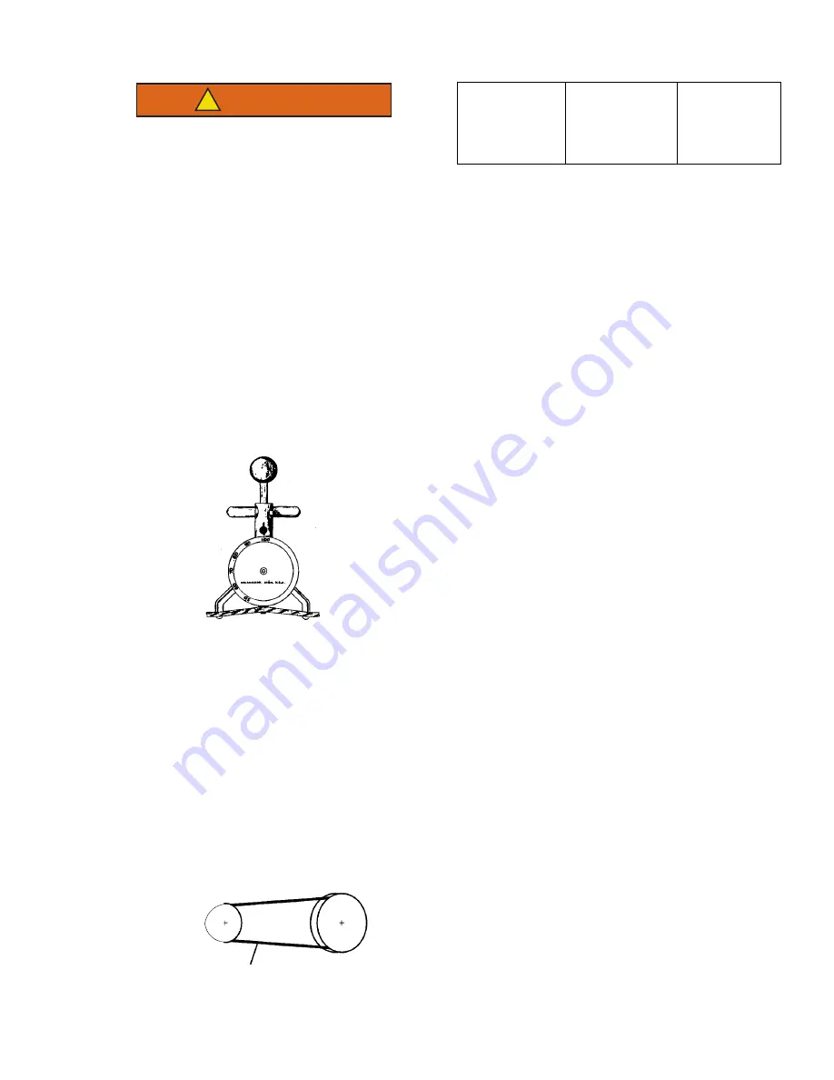
A belt tension gauge provides an accurate and easy
method of adjusting belts to their proper tension. Prop-
erly adjusted belts give long lasting and efficient service.
Too much tension shortens belt and bearing life, and too
little tension causes slippage and excessive belt wear. It
is also important to keep belts and sheaves free of any
foreign material which may cause the belts to slip.
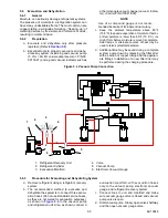
The Belt Tension gauge can be used to adjust all belts.
The readings which we specify for Carrier Transicold
units are applicable only for our belts and application,
as the tension is dependent on the size of the belt and
distance between sheaves. When using this gauge, it
should be placed as close as possible to the midpoint
between two sheaves.
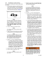
Figure 5.1 Belt Tension Gauge
Belt tension depends on each kit. Refer to Installation
Instructions provided with the kit for belt tension
requirements. In each kit installation instruction, we
indicate the belt tension (given with belt tension gauge
P/N 07-00203-00.
When installing a new V-belt the tension should be
somewhat higher than specified and readjusted after
allowing the unit to run for some time.
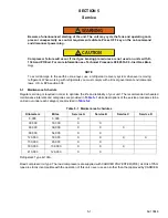
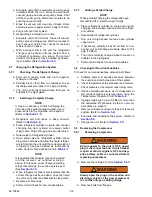
Figure 5.2 Layout of V-Belt
5.2.1
Standby Motor-Compressor V-Belt
a. Loosen the retaining bolts of the standby motor
support plate.
b. Replace the V-belt. Position the motor to correct
belt tension. Tighten the motor retaining bolts.
5.3
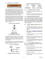
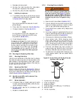
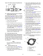
Installing R-134A Manifold Gauge Set
A R-134a manifold gauge/hose set with self-sealing
hoses is required for service of models covered within
this manual. The manifold gauge/hose set is available
from Carrier Transicold. (Carrier Transicold P/N 07-
00294-00, which includes items 1 through 6,
). To perform service using the manifold gauge/hose
set, do the following:
5.3.1
Preparing Manifold Gauge/Hose Set For
Use
a. If the manifold gauge/hose set is new or was
exposed to the atmosphere it will need to be
evacuated to remove contaminants and air as
follows:
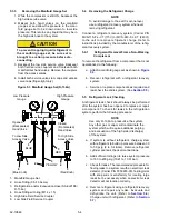
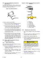
b. Back seat (turn counterclockwise) both field ser-
vice couplers (see
) and midseat both
hand valves.
c. Connect the yellow hose to a vacuum pump and
an R-134a cylinder.
d. Evacuate to 10 inHg (254 mmHg) and then
charge with R-134a to a slightly positive pres-
sure of 1.0 psig (0.07 Bar).
e. Front seat both manifold gauge set hand valves
and disconnect from cylinder. The gauge set is
now ready for use.
5.3.2
Connecting Manifold Gauge/Hose Set
To connect the manifold gauge/hose set for reading
pressures, do the following:
a. Remove access valve cap.
b. Connect the field service coupler (see
) to the access valve.
c. Turn the field service coupling knob clockwise,
which will open the system to the gauge set.
d. Read system pressures.
e. Repeat the procedure to connect the other side
of the gauge set.
Carrier Part Number 07-00203-00
Standby
Motor
Compressor
Standby Motor/Compressor V-Belt
Table 5–3 Belt Tension (See
)
BELTS
New Install
Tension
Running
Tension
Standby Motor
to Compressor
90 ft./lbs
(122 Nm)
80 to 90 ft./lbs
(108 to 122 Nm)
Содержание INTEGRA 30S
Страница 2: ......
Страница 4: ......
Страница 8: ......
Страница 14: ...62 11868 1 8 ...
Страница 18: ......
Страница 32: ......
Страница 40: ......
Страница 60: ......
Страница 62: ......
Страница 64: ......
Страница 65: ...62 10848 Figure 7 2 Electrical Schematic Wiring Diagram Based On Dwg No 62 61350 Rev E ROAD ONLY ...
Страница 66: ......
Страница 69: ......


