5-7
62-10848
c. Release and remove belt.
d. Remove the bolts mounting the compressor.
Remove the compressor from chassis.
e. Remove the pulley from the compressor.
5.9.2
Installing Compressor
a. To install the compressor, reverse the procedure
outlined when removing the compressor. Refer
to
for torque values.
NOTE
The service replacement compressor is sold
without flanges.
b. Pump down the compressor. (See
c. Charge compressor. (See
)
NOTE
It is important to check the compressor oil
level of the new compressor and fill if neces-
sary. (Refer to
d. Check refrigerant cycles.
Compressor oil type
: The road compressors
are supplied with CARRIER POLYESTER
(POE) oil. Ensure compressor is marked with a
factory sticker indicating the correct oil has
been installed. Oils of PAG type are
strictly
incompatible
with the operation of this unit,
never use an oil other than that approved
by CARRIER
.
5.10 Checking and Replacing Filter Drier
5.10.1
Checking Filter Drier
Check for any obstruction of the filter drier by feeling
the inlet and outlet connections of the liquid line on the
filter cartridge. If the temperature of the outlet connec-
tion seems lower than the temperature of the inlet con-
nection, replace the filter drier.
5.10.2
Replacing Filter Drier
Remove refrigerant charge (See
). Remove
the drier mounting clip, then replace the filter drier. Fol-
lowing drier replacement, evacuate and recharge unit
(refer to
).
5.11 High Pressure (HP1) and Condenser Pres-
sure (HP2) Switches
5.11.1
Removing Switch
a. A Schrader valve is located under each switch
to allow removal and installation without remov-
ing the refrigerant charge.
b. Remove switch and test in accordance with
c. Replace or reinstall switch.
5.11.2
Checking Pressure Switch
WARNING
!
Do not use a nitrogen cylinder without a
pressure regulator. (See
) Cylin-
der pressure is approximately 2350 psig
(160 bars). Do not use oxygen in or near a
refrigerant system as an explosion may
occur.
a. Remove switch as outlined in
.
b. Connect ohmmeter across switch terminals. Ohm-
meter will indicate resistance if switch is closed
(HP1) or open (HP2) after relieving pressure.
c. Connect switch to a cylinder of dry nitrogen (see
d. Set nitrogen pressure regulator higher than cut-out
point on switch being tested. Pressure switch set-
tings points are provided in
.
e. Close valve on cylinder and open bleed-off valve.
f. Open cylinder valve. While observing meter,
slowly close bleed-off valve and increase pres-
sure until the switch opens (HP1) or closes
(HP2). Slowly open bleed-off valve (to decrease
pressure) until switch reverts to normal position.
g. The meter will indicate open. Open pressure on
gauge. Slowly open bleed-off valve (to decrease
pressure) until switch closes (ohmmeter will move).
h. If switch does not activate within tolerances pro-
vided, replace switch. Test new switch before
installation.
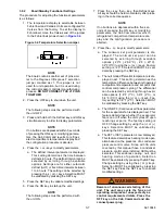
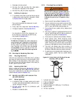
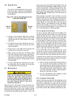
Figure 5.5 Typical Setup for Testing Pressure
Switches HP1 and HP2
1. Cylinder Valve and Gauge
2. Pressure Regulator
3. Nitrogen Cylinder
4. Pressure Gauge (0 to 400 psig = 0 to 28 bars)
5. Bleed-off Valve
6. 1/4 inch connection
Содержание INTEGRA 30S
Страница 2: ......
Страница 4: ......
Страница 8: ......
Страница 14: ...62 11868 1 8 ...
Страница 18: ......
Страница 32: ......
Страница 40: ......
Страница 60: ......
Страница 62: ......
Страница 64: ......
Страница 65: ...62 10848 Figure 7 2 Electrical Schematic Wiring Diagram Based On Dwg No 62 61350 Rev E ROAD ONLY ...
Страница 66: ......
Страница 69: ......

