2-7
62-10848
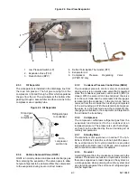
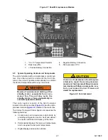
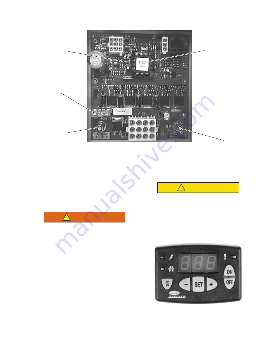
Figure 2.7 Road Microprocessor Module
1. °C or °F Temperature Selector
2. Road fuse (25A)
3. + Positive Battery Connection
4. - Negative Battery Connection
5. - Microprocessor (PC)
2.5
System Operating Controls and Components
The unit is furnished with a microprocessor control sys-
tem. Once the set point is entered at the Cab Com-
mand, the unit will operate automatically to maintain
the desired temperature within very close limits.
WARNING
!
Beware of unannounced starting of the
standby motor, evaporator fan or con-
denser fan. The unit may cycle the
standby motor or fans unexpectedly as
control requirements dictate.
The control system consists of the Cab Command
located in the driver’s section (
) and the micro-
processor module (
) located in the control box.
The Carrier Transicold Control System incorporates the
following features:
a. Control return air temperature to tight limits by
providing refrigeration control, heat and defrost
to ensure conditioned air delivery to the load.
b. Permanently displays the return air temperature
and on request the set point temperature.
c. Digital display and selection of data.
CAUTION
!
Under no circumstances should anyone
attempt to repair the microprocessor
module or Cab Command! Should a prob-
lem develop with these components, con-
tact your nearest Carrier Transicold
dealer for replacement.
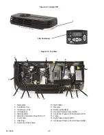
Figure 2.8 Cab Command
Содержание INTEGRA 30S
Страница 2: ......
Страница 4: ......
Страница 8: ......
Страница 14: ...62 11868 1 8 ...
Страница 18: ......
Страница 32: ......
Страница 40: ......
Страница 60: ......
Страница 62: ......
Страница 64: ......
Страница 65: ...62 10848 Figure 7 2 Electrical Schematic Wiring Diagram Based On Dwg No 62 61350 Rev E ROAD ONLY ...
Страница 66: ......
Страница 69: ......


