62-10848
3-4
3.4
Manual Defrost
Check that refrigerated compartment temperature is
40°F (4.4°C) or lower.
3.5
Defrost Cycle Adjustment
Defrost parameters may be set to eliminate defrost,
decrease the time between defrosts, allow full auto-
matic defrost, increase the time between defrosts or
set a forced interval between defrosts. To adjust the
defrost cycle, do the following:
1. Press the OFF key to shut down the unit.
2. Press the Manual Defrost and ON keys to dis-
play parameters.
3. Press the + or - keys to modify parameters.
4. Press the SET key to validate the modified set-
tings. This will return the display to the refriger-
ated compartment temperature.
NOTE
If no key is pressed within five seconds of
adjusting settings, the system reverts to dis-
playing the refrigerated compartment tem-
perature. Only validated changes are
recorded.
3.6
Alarm Display
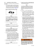
In the event of a malfunction, the unit will shut down
and the Cab Command will display an error message
or alarm message. The message will remain displayed
until the malfunction is corrected. If standby power is
connected and the malfunction is such that standby
operation can be allowed, the unit will start in the
standby mode.
3.6.1
Accessing Alarm Messages
To access the alarm messages:
1. Press the SET key for five seconds. This
enables access to alarm messages.
2. In the event of more than one alarm, press the +
or - keys to list them.
Press manual defrost key to initiate
manual defrost.
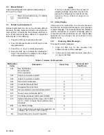
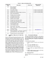
Table 3–1 Alarms For Road Units
Malfunction
Codes
Description
Alarm Only
Alarm and Unit
Shut Down
A00
Red LED flashes
No malfunction.
Unit in operation.
A01
High or Low pressure switch
X
A02
High or Low pressure switch
X
A04
Road clutch malfunction
X
A06
Condenser fan motor fault
X
A07
Evaporator fan motor fault
X
A09
Hot gas solenoid valve malfunction (HGS1)
X
A10
Quench valve malfunction (BPV)
X
A11
Condenser pressure control valve (HGS2)
X
A15
Setpoint adjusted out of the range -20.2 to 86°F (-
2 9°C / + 30°C) or below the programmed low
threshold.
X
BAT
Low battery voltage
X
EE
Probe malfunction or evaporator temperature out
of limits [- 49° to 174°F (- 45° to 79°C)]
X
Err
Programming error on part of operator
X
Содержание INTEGRA 30S
Страница 2: ......
Страница 4: ......
Страница 8: ......
Страница 14: ...62 11868 1 8 ...
Страница 18: ......
Страница 32: ......
Страница 40: ......
Страница 60: ......
Страница 62: ......
Страница 64: ......
Страница 65: ...62 10848 Figure 7 2 Electrical Schematic Wiring Diagram Based On Dwg No 62 61350 Rev E ROAD ONLY ...
Страница 66: ......
Страница 69: ......

