Important:
Don’t forget to protect
all
bare car-
bon edges with a length of the supplied silicone
tube, split with a knife and glued in place with
CA as shown. This is
very important
as any
wires or insulating material rubbing on the car-
bon will be cut thru’ in 1 flight - which can cause
a dangerous short circuit.
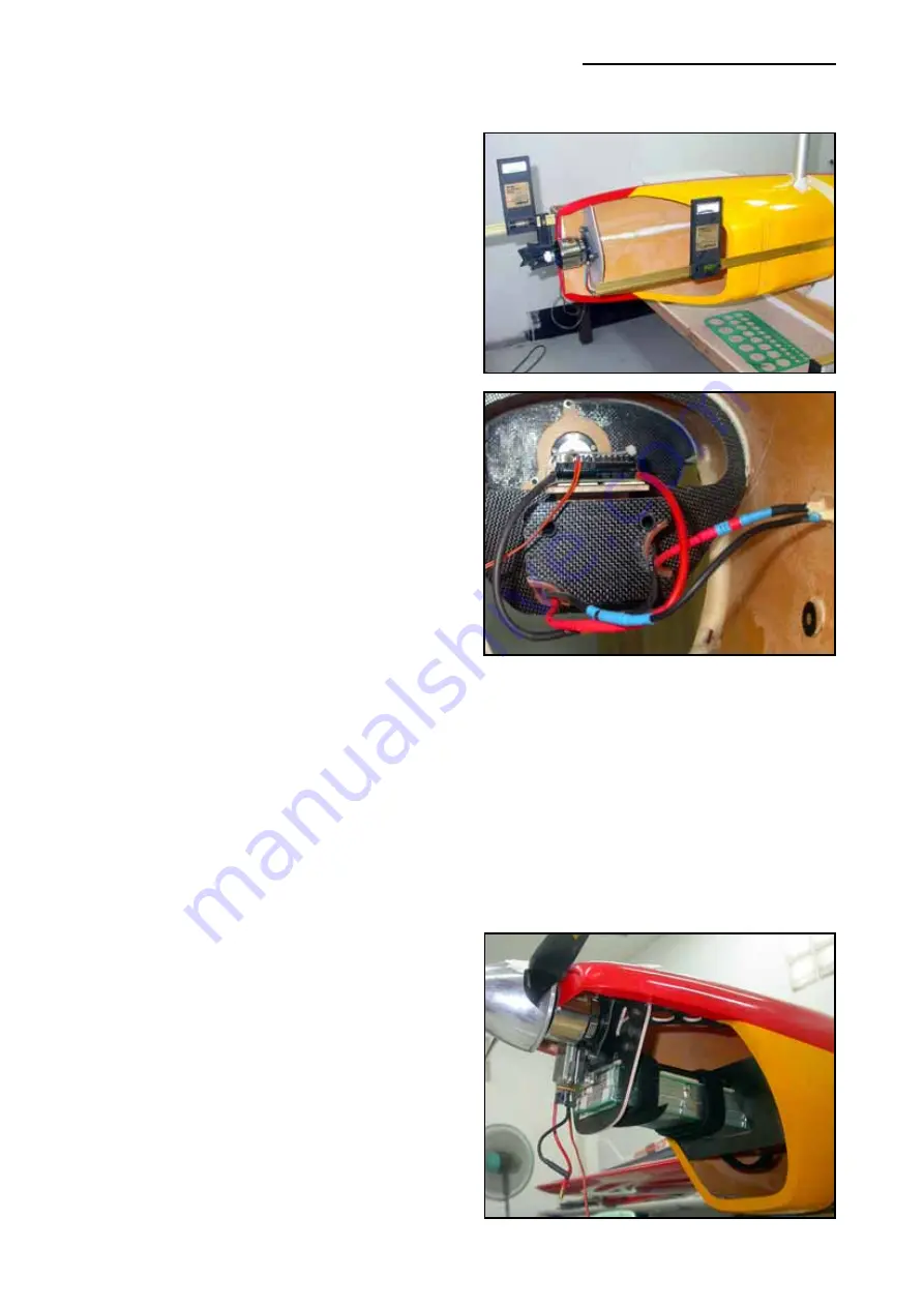
It is important to note that the front bulkhead is
glued into the fuselage with a 0° up/down thrust
setting, but with the 3° sidethrust. An easy way
to set this is to put the fuselage on it’s side, with
the wing spar in place and use a spirit level to
make it absolutely vertical (see photo -
Plettenberg motor shown). Then use an inci-
dence meter (Robart shown) on the centreline
seam of the fuselage to set the zero thrust line -
adjusting the height of the back of the fuselage
to get the 0°. Install the motor in the front bulk-
head and fit the incidence meter to the shaft of
the motor, and adjust until you have the required
3° sidethrust. Tack glue in position with thick CA,
also checking that the bulkhead is perpendicular
to the cowling flanges which are at 0° incidence.
Remove the motor carefully, and glue the bulk-
head in securely with slow epoxy and micro-balloons. Tack glue the the middle bulkhead in place
in the same way, but with NO sidethrust, and fit the motor again, using the plywood part with the
3 ‘ears’ to fine tune the upthrust and sidethrust angles. Mark the holes for the M3 bolts and fit
with blindnuts to secure the motor. The slight flexibility allowed by the plastic grommets used to
mount the motor to the front bulkhead will allow about 0.5 - 1° thrustline adjustment.
The middle and rear bulkheads can be tacked glued in position with a little thick CA, using the
carbon tubes for alignment, and then fixed securely in the same manner as the front bulkhead
with 30minute or 24hr epoxy and microballoon mix.
Plettenberg Xtra 25-13.
The Plettenberg motor is mounted in a similar
manner, except that there is no bulkhead in front
of the motor - as the
outside
of the motor turns.
This installation is a little more lightweight than
the Hacker set-up, with only 2 main bulkheads
and a support plate. We also used an Emcotec
DPSI LR voltage regulator to take power from
the flight batteries (Emcotec LongGo 10S2P
4000mAH LiPo's) to supply the receiver, saving
the extra weight of a separate Nicad. To get the
correct ‘C of G’ with this set-up you must put all
components as far forward in the plane as pos-
sible, including the rudder servo, and be very
Composite-ARF Extra 330L
(2.6m span)
27
Plettenberg Xtra 25-13 shown
Hacker shown
Plettenberg Xtra 25-13


