The batteries (Emcotec LongGo
LiPo's 10S2P 4000 mAH) are
mounted in a similar way as for the
Hacker, with a small piece of foam-
board glued onto the carbon tubes,
and retained with Velcro straps pro-
vided in the E-option pack.
The speed controller used with the
Plettenberg was a Schulze ‘Future
32.55’, which is a very nice light-
weight unit, but has short connecting wires to the batteries.
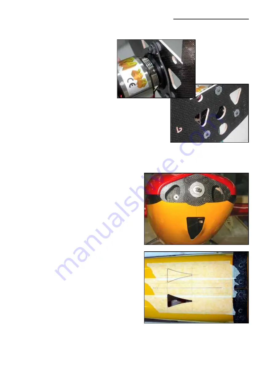
Therefore it was mounted on the side of the front bulkhead
next to the motor (with Velcro), and the connections to the
LiPo cells are made at the front. Make sure that sufficient
cooling air is directed to the speed controller in this location.
Plettenberg recommend a RASA 18 x12 carbon
prop for this motor.
Cooling:
Depending on your choice of motor, battery and
speed controller you will need to make provision
for enough cooling to all these components dur-
ing flight. All 3 components will get warm during
use, but must not get too hot to prevent damage
and possible damage or fire.
This is
most important
, and if this is your 1st
electric model we
strongly
recommend that you
follow the advice of the manufacturers, and this
instruction manual. Different power unit and bat-
tery combinations will operate at different tem-
peratures in different ambient climates, so it is
not possible to give you the exact areas and
positions of the cooling required for every set-
up. However, the cooling cut-outs shown in the
photos here, in addition to the large air exit in the
bottom/rear of the cowling, have worked well
with the installations we have tested.
You should go towards
more
cooling, rather than
less, and pay particular attention that the area of
the
exit
area for the cooling airflow is at least
20% bigger than the air entry area. Open up the
cooling entrance in the lower front of the cowling
to it’s maximum width (about 40mm) and make
it V-shaped about 90mm long as shown in the photos. Cut out the full oval shape in the front of
the cowling around the spinner, as shown in the Hacker installation, and make sure to have some
holes in the bulkheads to allow the air to pass freely around all components. We also made 2
(70mm long) NACA style air outlets in the bottom of the fuselage (see photo), just behind the
landing gear, to ensure that warm air is able to get out of the fuselage. Don’t cut through the 1”
Composite-ARF Extra 330L
(2 x 2m)
29


