background image


docs.carbide3d.com 

Final Assembly Box 

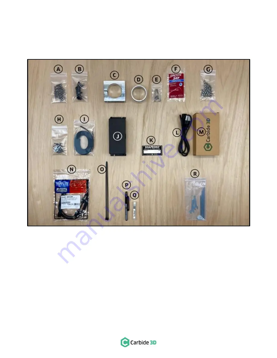
Carefully open the box labeled XXL Final Assembly and inspect its contents. Many parts are packaged in small plastic 
bags, and smaller bags may be inserted into larger bags for shipping purposes. This box should contain all of the items 
shown in 

Figure 1-2 

and listed in the table on the next page. 


Figure 1-2 

Содержание SHAPEOKO XXL

Страница 1: ...X X L A S S E MB L Y G U I D E ...

Страница 2: ...leanup 55 Step 10 Compact Router 58 Step 11 Level and Square 63 Connect to Power 65 Download the Software 65 Configure Carbide Motion 5 66 Run the Test Project 67 Workholding 68 Cutting Tutorials and Projects 69 User Guides and Video Tutorials 69 Have Questions Need Help We have a fully staffed support department waiting to help you if you run into trouble while assembling your Shapeoko XXL Just s...

Страница 3: ...nstructed to do so Firmware The Shapeoko XXL controller unit ships with GRBL 1 1 firmware which must be used with Carbide Motion 5 This document supersedes any information you may find on the Carbide 3D website Stepper Motors Your Shapeoko XXL is powered by stepper motors When the power is off moving the motors by hand will cause them to generate electricity WARNING This is a warning Information i...

Страница 4: ... operating the machine and check in with them after successfully completing work Never allow children to use the Shapeoko XXL unsupervised Fire Prevention Consider the possibility of a fire caused by friction from the router and take suitable fire prevention precautions e g having a fire extinguisher handy and other suitable precautions Outlet Requirements Plug the router into an outlet that has a...

Страница 5: ...ions so that it projects at least as much as the deepest intended cutting depth Check to make certain that the collet is tight and will not work loose during operation it needs to be more than finger tight the machine will take no notice or care if it works loose 6 Clear the Work Area Ensure the work area is clear and all cables run without interference Most importantly check that there is nothing...

Страница 6: ...ails which as you ll see as we begin to assemble the Shapeoko XXL that this allows the carriages to slide easily along the rail system End Mill or End Mill Cutter End mills or cutters are the cutting tools used by a CNC machine End mills are similar to drill bits though typically they can cut in all directions End mills come in several varieties including square ball nose and v carving and lots of...

Страница 7: ...H Cross Strap Package 1 40 x 7 x 1 5 Package Contains 3 Identical Cross Straps I Aluminum Extrusion Rail Package 1 40 x 7 5 x 3 5 Package Contains 3 Unique Extrusion Rails J Endplate Package 1 45 5 x 8 x 2 Package Contains 2 Identical Endplates K MDF Baseplate Board 2 42 x 29 75 x 0 75 2 Identical Boards Under Divider Optional Items L Carbide Compact Router Box 1 Contains the Compact Router and Ac...

Страница 8: ...XL Final Assembly and inspect its contents Many parts are packaged in small plastic bags and smaller bags may be inserted into larger bags for shipping purposes This box should contain all of the items shown in Figure 1 2 and listed in the table on the next page Figure 1 2 ...

Страница 9: ...m Button Head Cap Screw 2 3 K Shapeoko Decal 1 L Power Cord 1 M Power Supply 1 N USB Cable 1 O Large Zip Tie 2 P Permanent Marker 1 Q 201 inch Square End Mill Cutter 1 R Tool Kit 5 4 3 2 5 2 and 1 5mm Hex Keys 10 and 8mm Wrenches 8 The 5mm hex key is provided in case you need to adjust the stepper motor idlers the 1 5mm hex key is provided in case you need to adjust the motor pulley set screws Y A...

Страница 10: ... Plates 2 and Hardware M3x18 4 M5x8mm 4 Socket Head Cap Screws 30mm Male to Female Standoffs 2 12 D Cable Tie Mounts 5 Cable Ties 25 and Hardware M4x6mm Socket Head Cap Screws 5 35 E PCB Riser Board Adapter Board for Proximity Switches 1 X Z Box Open the box labeled X Z and visually verify that the items inside match those shown in Figure 1 5 Item Description Qty A Z Plus Carriage with Z Axis Step...

Страница 11: ...il has two 2 M6 and four 4 M4 pre drilled screw holes along one side Y Axis Right Rail Y2 rail has two 2 M6 pre drilled screw holes along one side Endplates The two 2 identical endplates are packed together Remove the cardboard shell and identify the two endplates shown in Figure 1 8 Cross Straps The three 3 cross straps are identical and are packed together in a cardboard shell Remove the packagi...

Страница 12: ...t are required for assembly see Figure 1 12 Item Description Qty A Flush Cut Pliers or Scissors 1 B Level 1 Recommended Tools The following tools are recommended for assembly but not included see Figure 1 12 Item Description Qty C 8 and 10mm Combination Wrench 2 D Easy Peel Masking Tape e g blue painter s tape nothing that leaves a residue behind 1 E Flashlight 1 F Tape Measure 1 G Ruler 1 Figure ...

Страница 13: ...onfusion all such references are given from the perspective of one standing in front of and looking at the machine as shown in Figure 1 13 As much as possible the words left and right are replaced with Y1 and Y2 respectively in reference to the Y Axis LEFT extrusion rail Y1 and the Y Axis RIGHT extrusion rail Y2 Take a minute to familiarize yourself with this view of the machine In addition to ado...

Страница 14: ...docs carbide3d com 12 Figure 2 2 Step 2 Baseframe ...

Страница 15: ...ate N A 2 D M5 x 25mm Button Head Cap Screw XXL Final Assembly Box 18 E Adjustable Leveling Foot XXL Final Assembly Box 4 Required Tools See Figure 2 3 Item Description Qty A 3mm Hex Key 1 B Level not included 1 Recommended Tools See Figure 2 3 Item Description Qty C Spare Hex Key included 2 or 3 D Flashlight 1 E Tape Measure 1 Figure 2 3 ...

Страница 16: ...e the 3mm hex key to insert three 3 M5x25mm button head cap screws through the three middle countersunk holes in the MDF baseplate and into the integrated nuts in the three cross straps as shown in Figure 2 6 4 Turn the screws until they stop but do not fully tighten Figure 2 4 Figure 2 5 Figure 2 6 WARNING Be careful to avoid cross threading screws WARNING Assembly should not be done on the floor...

Страница 17: ...gure 2 8 3 Adjust the endplate cross straps and MDF baseplates so that all six holes align Use one or more of the spare hex keys to help with alignment as shown in Figure 2 9 4 Use the 3mm hex key to insert six 6 M5x25mm button head cap screws into the six countersunk holes in the MDF baseplate through the cross straps and into the integrated nuts of the rear endplate See Figure 2 9 5 Turn the scr...

Страница 18: ... the cross straps and into the front endplate 4 Turn the screws until they stop but do fully tighten Figure 2 10 Figure 2 11 Figure 2 12 PRO TIP To further help with hole alignment shine a flashlight under the assembly to illuminate the holes from the bottom Adjust as necessary See Figure 2 10 PRO TIP You can also try loosely inserting screws from the center and working your way out i e center lef...

Страница 19: ...measuring diagonally across the baseframe from the outside edges of the endplates Check both sides The machine is square when the two measurements are equal See Figure 2 14 Approximates are acceptable at this stage as the machine is not fully tightened A final and more comprehensive leveling and squaring of the machine will be completed in Step 11 Level and Square Figure 2 13 Figure 2 14 WARNING T...

Страница 20: ...docs carbide3d com 18 Figure 3 2 Step 3 Carriages ...

Страница 21: ...4 I Tramming Plate X Z Box 1 J M5 x 8mm Socket Head Cap Screw X Z Box 4 K Router Mount XXL Final Assembly Box 1 L M5 x 55mm Socket Head Cap Screw XXL Final Assembly Box 2 M M5 x 16mm Button Head Cap Screw XXL Final Assembly Box 2 N Router Mount Adapter Ring XXL Final Assembly Box 1 O Loctite 242 Threadlocker XXL Final Assembly Box 1 P Y Axis Right Carriage Y2 Carriage Y Axis Right Assembly Box 1 Q...

Страница 22: ...tral spacer with offset threads now acts as a cam converting the rotational motion of turning the eccentric nut into linear motion at the V wheel The dimple on the side of the nut is a reference point to the widest distance to the offset threads When the dimple is facing up the lower V wheel is at its farthest distance from the fixed upper V wheel the V wheel is OPEN When the dimple is down the V ...

Страница 23: ... Figure 3 4 if needed Assemble the Z Plus Attaching the X Motor Take a minute to familiarize yourself with the features and layout of the Z Plus See Figure 3 7 1 Place the Z Plus face down with the six 6 pre installed 30mm standoffs pointing up 2 Set the X motor onto the four 4 evenly spaced 30mm standoffs in the center of the Z Plus between the Z motor and the idlers with the Carbide 3D label fac...

Страница 24: ... it must be properly oriented with the smallest hole fixed point in the top left corner This is the FRONT of the tramming plate 1 Position the tramming plate with the short legs extending up in a U shape 2 Carefully inspect the top two holes shown in Figure 3 10 3 Determine which of the holes is smaller and position the tramming plate with this hole at TOP LEFT This is the FRONT of the plate Figur...

Страница 25: ...mming plate and fully tighten See Figure 3 11 Attaching Tramming Plate to Z Plus 1 Place the Z Plus face UP resting on the X motor Z motor pointing away from you 2 Position the router mount with Carbide 3D logo upright and tramming plate resembling the letter U Place it onto the front of the Z Plus and align the four 4 tramming plate through holes with the four 4 available M5 screw holes on the fr...

Страница 26: ...the front and sixteen 16 pre drilled M4 screw holes along the back It will be positioned left to right with the v rail facing front b Y Axis left aluminum extrusion rail Y1 rail has two 2 pre drilled M6 screw holes and four 4 pre drilled M4 screw holes along the outside It will be installed on the left side of the machine running front to back with the v rail facing to the inside c Y Axis right al...

Страница 27: ...lly tighten the screws Figure 3 17 Figure 3 16 PRO TIP Screws going into the ends of the extrusion rails are prone to cross threading Pre screw without the carriage present to clear any debris from the threads Screws should thread easy with little resistance and without wobble Also when attaching the carriage partially insert each of the four 4 screws before tightening Tighten a little at a time i...

Страница 28: ...he Y2 Carriage 1 Locate the Y2 carriage 2 Use the 4mm hex key and four 4 M6x12mm button head cap screws to attach the Y2 carriage to the right end of the X rail See Figure 3 20 When properly attached the motor body will be to the inside and behind the X rail The V wheels idlers and motor pulley will be facing out as shown in Figure 3 20 3 Snug the Y2 carriage to the X rail but do not fully tighten...

Страница 29: ...support carbide3d com 27 Figure 4 2 Step 4 Gantry ...

Страница 30: ...crew XXL Final Assembly Box 8 B Y Axis Right Aluminum Extrusion Rail Y2 Rail N A 1 C M6 x 12mm Button Head Cap Screw XXL Final Assembly Box 8 Required Tools See Figure 4 3 Item Description Qty A 4mm Hex Key 1 B 10mm Wrench 1 C Foam Packing Block From the Two Y Carriage Boxes 2 Recommended Tools See Figure 4 3 Item Description Qty D 10mm Combination Wrench 1 Figure 4 3 ...

Страница 31: ...he Y rails is crucial The Y1 rail will be installed on the left the Y2 rail on the right Positioning the X Rail 1 Position the X rail with attached carriages diagonally across the baseframe See Figure 4 6 Figure 4 4 Figure 4 5 Figure 4 6 PRO TIP Test fit the Y1 and Y2 rails between the endplates If the fit is too tight loosen the twelve 12 screws holding the MDF baseplates to the endplates to give...

Страница 32: ...ils are positioned between the front and rear endplates The Y1 rail should be along the left the Y2 rail along the right and the Z Plus facing front See Figure 4 9 Securing the Y1 Rail The Y1 and Y2 rails will be raised into place one at a time The first rail to be lifted the Y1 rail is loosely attached to the endplates with two 2 screws one front and one back This creates a pivot point for rotati...

Страница 33: ... Y2 rail to the front and rear endplates See Figure 4 11 Completing Rail Assembly 1 Use the 4mm hex key and the remaining six 6 M6x12mm button head cap screws to completely secure the Y 1 rail to the front and rear endplates 2 Snug all sixteen 16 screws leaving no gap between the rails and endplates but do not fully tighten Tension the V Wheels 1 Use the 10mm wrench to turn the two 2 eccentric nut...

Страница 34: ...docs carbide3d com 32 Figure 5 2 Step 5 Belting ...

Страница 35: ...drive the gantry Belts are secured to the rail using belt clips Each right angle belt clip has an integrated PEM nut on the short leg and two parallel slots on the long leg All six belt clips attach to the belts in the same way follow the process described below and shown in Figure 5 4 1 Thread 2 1 2 inches of belt through the outer slot of the belt clip with teeth facing in toward the PEM nut 2 L...

Страница 36: ...ne 1 M5x10mm socket head cap screw to attach the belt clip to the Y1 carriage Insert the screw from the OUTSIDE and tighten See Figure 5 5 4 Feed the belt under the two idlers on the back of the Z Plus Make sure the belt does not twist and the teeth remain facing down all the way to the Y2 carriage See Figure 5 6 Do not attach the other end of the belt just yet 5 Slide the 3mm hex key under the be...

Страница 37: ...lling the free end toward the Y2 carriage 8 Attach another belt clip to the other end of the belt Refer back to Figure 5 4 9 Adjust the amount of belt you feed through the second belt clip so that when it s laid flat against the X rail with the slack removed but without stretching it a 1 4 inch gap exists between the belt clip and the Y2 carriage Ensure the teeth of the bottom few inches of belt i...

Страница 38: ... The belt should lay flat teeth down and extend along the Y1 rail towards the Y1 carriage Ensure the teeth of the bottom 2 inches of belt interlock with the top See Figure 5 12 3 Use the 4mm hex key and one 1 M5x10mm socket head cap screw to attach the belt clip to the front endplate Insert the screw from the FRONT and tighten See Figure 5 12 4 Feed the belt under the two idlers on the outside of ...

Страница 39: ... the second belt clip so that when it s laid flat against the Y1 rail with the slack removed but without stretching it a 1 4 inch gap exists between the belt clip and the rear endplate Ensure the teeth of the bottom few inches of belt interlock with the top 11 Use the 4mm hex key and one 1 M5x10mm socket head cap screw to attach the belt clip to the rear endplate Insert the screw from the BACK SID...

Страница 40: ...docs carbide3d com 38 Figure 6 2 Step 6 Drag Chains ...

Страница 41: ...p Screw Wiring Harness Box 2 I M3 x 4mm Flat Head Screw Wiring Harness Box 1 Y AXIS DRAG CHAIN SUPPORT SYSTEM J Y Axis Drag Chain Head Bracket Wiring Harness Box 1 K M5 x 16mm Socket Head Cap Screw Wiring Harness Box 2 L M5 Nut Wiring Harness Box 2 M M3 x 4mm Flat Head Screw Wiring Harness Box 2 N Drag Chain Support Bracket Wiring Harness Box 1 O M4 x 6mm Socket Head Cap Screw Wiring Harness Box 2...

Страница 42: ...the head bracket to the back of the Z Plus just above the X motor See Figure 6 4 3 Use the 3mm hex key and two 2 M4x6mm socket head cap screws to attach one 1 drag chain support bracket to the back of the X rail closest to the Y2 carriage 4 Repeat with the second support bracket in the center of the X rail See Figure 6 5 5 Use the 3mm hex key and two 2 M4x6mm socket head cap screws to attach one 1...

Страница 43: ...rt brackets 2 Use the 8mm wrench and two 2 M5 nuts to secure the head bracket to the two protruding M5x16mm socket head cap screws on the Y1 carriage above the Y1 motor pulley See Figure 6 7 3 Use the 3mm hex key and two 2 M4x6mm socket head cap screws to attach the support bracket no PEM nut to the outside of the Y1 rail Install closest to the front endplate See Figure 6 8 4 Use the 3mm hex key a...

Страница 44: ...e 6 9 WARNING Be careful when handling the wiring harness not to damage any of the proximity switches or stepper motor extensions and connectors Also the drag chains will only curl in one direction Do not force the drag chain to bend if it doesn t curl easily simply turn it over and try again ...

Страница 45: ...s tail being next to the controller unit and head on the Y1 carriage X Axis Drag Chain The X Axis drag chain rests on the X rail and serves as the protective housing for only four of the cables the X and Z extension cables the X Axis proximity switch and the Z Axis proximity switch extension It has 54 chain links with its tail being next to the Y1 carriage and head on the Z plus Stepper Motor Exte...

Страница 46: ...t at the front See Figure 6 12 4 Use the 2mm hex key and two 2 M3x4mm flat head screws to secure the Y Axis drag chain to the head bracket as shown in Figure 6 13 5 Use the 2mm hex key and one 1 M3x4mm flat head screw to attach the drag chain to the single PEM nut in the tail bracket at the rear Use the center through hole closest to the end of the drag chain See Figure 6 14 Figure Error No text o...

Страница 47: ...p and towards the Z Plus and rest it on top of the X Axis drag chain head bracket See Figure 6 15 3 Use the 2mm hex key and two 2 M3x4mm flat head screws to secure the X Axis drag chain to the head bracket See Figure 6 15 4 Use the 2mm hex key and one 1 M3x4mm flat head screw to attach the tail of the drag chain to the single PEM nut in the tail bracket Use the center through hole closest to the e...

Страница 48: ...docs carbide3d com 46 Figure 7 2 Step 7 Proximity Switches ...

Страница 49: ...ess Box 2 I Cable tie Wiring Harness Box 1 Required Tools See Figure 7 3 Item Description Qty A 2 5 and 4mm Hex Key 2 Install the Proximity Switches The Shapeoko XXL includes three inductive proximity switches The Z Axis proximity switch is pre installed on the front of the Z Plus The X and Y Axis switches are pre installed in the wiring harness See Figure 7 4 Installing the X Axis Proximity Switc...

Страница 50: ...offs at the rear of the Z Plus See Figure 7 6 6 Use one 1 cable tie to secure the proximity switch cable to the upper standoff See Figure 7 6 Installing the Y Axis Proximity Switch The Y Axis proximity switch exits the Y Axis drag chain at the Y1 carriage It attaches to the Y Axis switch plate then mounts to the OUTSIDE of the Y2 carriage 1 Locate the Y Axis proximity switch mounting plate and the...

Страница 51: ...se one 1 cable tie to secure the proximity switch cable to the upper standoff See Figure 7 9 Connecting the Z Axis Proximity Switch 1 Locate the short black Z Axis proximity switch cable exiting the back of the Z Plus and the long gray 3 pin extension cable labeled Z exiting the head of the X Axis drag chain 2 Properly align and connect the two cables See Figures 7 10 and 7 11 Figure 7 8 Figure 7 ...

Страница 52: ...docs carbide3d com 50 Figure 8 2 Step 8 Wiring ...

Страница 53: ...er Board The PCB requires an adapter to wire the polarized 3 pin inductive proximity switches to the controller board 1 Remove the three 3 thumb screws holding the cover in place 2 Use the 2mm hex key to remove the one 1 M3x6mm flanged button head screw 3 Carefully remove the controller unit cover Inside the controller unit you will find two 2 M6x12mm button head cap screws which are used to mount...

Страница 54: ...ontroller Unit All of the proximity switch and stepper motor extension cables exit the drag chain at the Y Axis drag chain tail bracket just above the controller unit Proximity switches use the 3 pin ports of the PCB riser board in the top right corner of the controller board Stepper motors use the 4 pin ports along the bottom of the controller board Refer back to Figure 8 4 Wiring Proximity Switc...

Страница 55: ...ller unit cover Connect the Stepper Motors Shapeoko XXL comes equipped with four stepper motors X Y1 Y2 and Z Each motor connects to the controller unit via a gray extension cable installed in the wiring harness at the factory Each cable has been labeled with its proper connection The X and Z motor extension cables exit the X Axis drag chain behind the Z Plus and the Y1 and Y2 motor cables exit th...

Страница 56: ...ion cable exits the head of the Y Axis drag chain 1 Unravel the Y1 motor leads 2 Connect the Y1 motor leads to the short gray 4 pin extension cable labeled Y1 See Figure 8 12 Connecting Y2 Axis Stepper Motor The Y2 motor is located on the Y2 carriage Its extension cable exits the head of the Y Axis drag chain 1 Unravel the Y2 motor leads 2 Extend the long gray 4 pin extension cable labeled Y2 abou...

Страница 57: ...support carbide3d com 55 Figure 9 2 Step 9 Cleanup ...

Страница 58: ... not included 1 C Sharpie Permanent Marker 1 Cleanup the Gantry Cables In this step we ll be securing loose cables with cable ties and cable tie mounts Securing Cables at the Y1 Carriage All seven 7 cables crossing the Y1 carriage plate are bundled into the circular cutout at the top of the carriage 1 One at a time insert the cables beginning with the three Y cables followed by the four X Z cables...

Страница 59: ...sh cut pliers or scissors not included Securing the Cables at the Z Plus The X Z cables are bundled neatly behind the Z Plus 1 Collect the X cables and neatly bundle them behind the X motor See Figure 9 7 2 Use one cable tie to secure the X cables to the first link of the drag chain and a second to keep the bundle tidy 3 Collect the Z cables and neatly bundle them behind the Z motor See Figure 9 7...

Страница 60: ...docs carbide3d com 58 Figure 10 2 Step 10 Compact Router ...

Страница 61: ... the Carbide Compact The Z Plus supports routers with a diameter of 65mm and 69mm Following are the installation steps for our 65mm Carbide Compact Router 65mm routers require the use of the included router mount adapter ring which we installed in a previous step In a previous step we also lowered the Z carriage on the front of the Z Plus to its lowest point 1 Use the 4mm hex key to loosen the two...

Страница 62: ...ack of the Z Plus See Figure 10 6 The router s power cord can cause electromagnetic interference EMI for the motor extension cables and the USB cable so we want to route it as far away from these cables as possible To begin we re going to create a two link cable tie chain with each link about 1 inch in diameter 3 Collect three 3 cable ties 4 Create the first 1 inch loop at the open attachment poin...

Страница 63: ... will secure the cable from the inside of the Y2 carriage plate See Figure 10 8 9 Once the router cable is positioned in the cutout tighten the all three 3 cable ties to secure the router in place See Figure 10 8 10 Trim down the ends of the two 2 cable ties on the outside of the Y2 carriage leaving about 1 2 inch at the end of each as shown in Figure 10 9 The short ends help hold the cable in pla...

Страница 64: ...a 13mm spindle wrench and the XXL kit comes with a 201 0 25 flat end mill Installing the End Mill 1 Clean and insert the end mill shank into the loosened collet a minimum of 0 75 20mm the entire length of the collet cone and nut See Figure 10 12 2 Use the 22mm collet nut wrench and the 13mm spindle wrench to tighten the collet nut securely See Figure 10 13 Alternatively you can press and hold the ...

Страница 65: ...m wrench to turn the eccentric nuts CLOCKWISE until the wheels engage with the v rail Confirm Level The baseframe assembly was given a preliminary leveling at the end of step 2 1 Use a level not provided to perform a comprehensive leveling of the machine now 2 Adjust the four 4 leveling feet up or down as needed 3 Check for level in several spots across the baseframe Front to back side to side and...

Страница 66: ...BACK of the machine 9 Place steady even rearward pressure on the X rail so that both Y carriages touch the REAR endplate 10 Use the 4mm hex key to fully tighten the eight 8 M6x12mm button head cap screws of the REAR endplate four 4 per side 11 Use the 3mm hex key to tighten the eighteen 18 M5x25mm button head cap screws securing the MDF baseplates to the baseframe Optional Use a tape measure to co...

Страница 67: ...r the motors begin to hum and a blue LED on the controller unit will be visible through a slit in the cover See Figure 12 2 Download the Software 1 Download Carbide Motion 5 from carbide3d com carbidemotion download 2 Download Carbide Create from carbide3d com carbidecreate 3 Install both programs to your computer Carbide Motion lets you control your machine by jogging it around setting zeroes and...

Страница 68: ...tings 1 Once your screen reads Job Info click the Settings button in the top menu bar to open Settings See Figure 13 2 2 Choose XXL from the Size dropdown list Z Plus Leadscrew from the Z Axis Type dropdown list and Inches from the Units dropdown list See Figure 13 3 3 Click the Update Shapeoko Configuration button in the middle of the dialog window See Figure 13 3 4 A progress bar will appear at ...

Страница 69: ... switches is triggered at which time they will follow the same pattern as the Z Axis engage the homing switch back off re engage and then back off again 2 When all three axes have homed your router will be in the back right corner Troubleshooting Homing Issues docs carbide3d com software faq home switch troubleshooting Run the Test Project Required Components See Figure 14 1 Item Description Qty A...

Страница 70: ... track system sits on top of your baseframe and provides a flexible reliable way to hold down material to your Shapeoko XXL The kit includes everything you need to add this system to your machine Purchase shop carbide3d com collections accessories products t track table Gator Tooth Clamps Gator Tooth Clamps are ultra low profile Use them as a backstop a side clamp or a toe clamp With over 30mm of ...

Страница 71: ...commend you browse through our Carbide 3D docs pages docs carbide3d com We ve packed the docs site full of all kinds of useful information to help you get up and running with your Shapeoko XXL and to help answer common questions you might run into User Guides and Videos Carbide Create Video Tutorials Watch the videos at docs carbide3d com assembly carbidecreate video tutorials Carbide Motion User ...

Отзывы: