background image


[email protected] 

docs.carbide3d.com


05/01/20  

v1.1


Option 2: Carbide Motion Board Modification 

Kit Option 2 includes a 6-pin BitRunner 
connector which needs to be soldered onto 
your existing Carbide Motion board. Use best 
practices when soldering onto the PCB. 

To modify the Carbide Motion board: 

1.


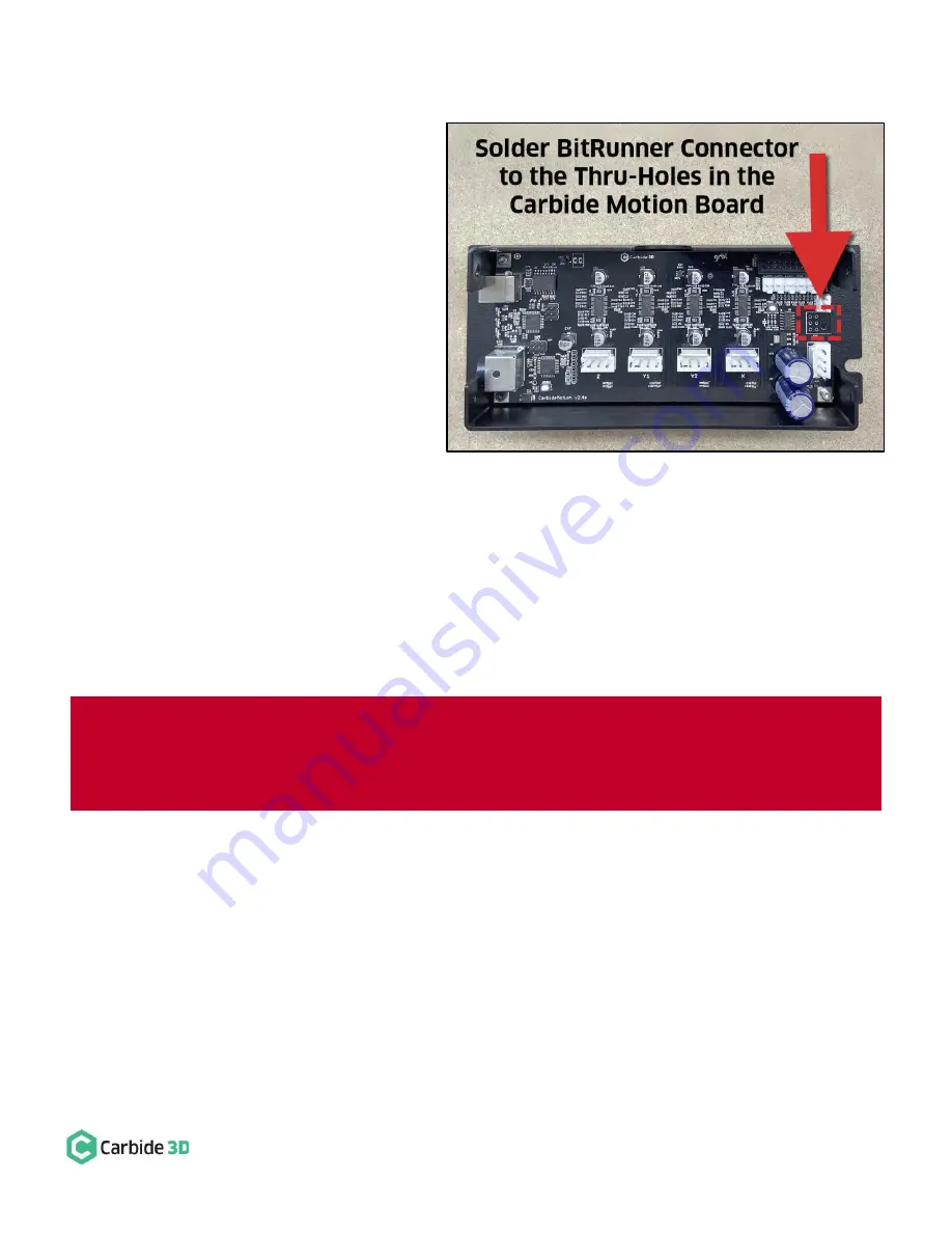
Solder the male 6-pin BitRunner 
connector to the board. Insert the 

connector’s alignment peg and six (6) 

solder pins into the six available thru-
holes on the right edge of the board. See 

Figure 5

. The connector points away 

from the enclosure (toward the FRONT 
of the machine). 

2.


Re-insert the modified board, 
USB/power end first, into the enclosure. 
The USB and power ports will slightly 
protrude from the BACK (left) of the enclosure. The 6-pin BitRunner connector protrudes from the 
FRONT (right). 

3.


Use an SAE 

3

/

32

-inch hex key and the four (4) existing socket head cap screws to secure the modified 

Carbide Motion board to the enclosure. 

4.


Use a 4mm hex key and two (2) M6x12mm button head cap screws to attach the enclosure to the 
Y1-rail with the USB and power ports at the BACK and the 6-pin BitRunner connector at the FRONT. 

5.


Reconnect the three (3) homing/proximity switch cables and four (4) stepper motor extension cables. 


6.


Install the new enclosure cover included in the BitRunner kit and secure with existing hardware. 

7.


Reconnect the power and USB cables at the rear of the Carbide Motion board. 


Figure 5 

WARNING:

 The new 6-pin BitRunner connector protrudes from the front of the Carbide Motion board 

enclosure. When installing the new cover, place it carefully over the BitRunner connector first, then bring it 
down over the USB and power ports.  If you should ever need to remove the cover, pry it open from the 
USB/p

ower end first, then open like a book to avoid d

amaging the Bitrunner connector.


Содержание BitRunner

Страница 1: ...Kit Item Description Qty Note A BitRunner 1 BitRunner enclosure and attached power cords B Communications Cable 1 Gray 6 pin male to female extension cable C Mounting Hardware 2 M6 x 12mm button head...

Страница 2: ...t carbide3d com and we will get you back on track Install the BitRunner Attach BitRunner to Y2 Rail Newer Models With Z Plus The BitRunner attaches to the two M6 holes on the outside of the Y2 rail wi...

Страница 3: ...unting holes is 6 10 155mm 3 Use a 5mm drill bit for the tap hole and an M6 tap to form the threads Be sure to drill all the way through the outer wall of the extrusion and into the cavity 4 Use a 4mm...

Страница 4: ...rail 5 Use an SAE 3 32 inch hex key to remove the four 4 socket head cap screws in the corners of the Carbide Motion board The Carbide Motion board is taped to the enclosure and will need to be gentl...

Страница 5: ...board enclosure to the Y1 rail with the USB and power ports at the BACK and the 6 pin BitRunner connector at the FRONT 6 Reconnect the three 3 homing proximity switch cables and four 4 stepper motor e...

Страница 6: ...e an SAE 3 32 inch hex key and the four 4 existing socket head cap screws to secure the modified Carbide Motion board to the enclosure 4 Use a 4mm hex key and two 2 M6x12mm button head cap screws to a...

Страница 7: ...rom the Y2 rail See Figure 6 Make sure the plug is fully seated You will hear the latch click into place Connect the Female End to the Carbide Motion Board The FEMALE end of the communications cable c...

Страница 8: ...1 Left Forward Auto On Off the LED is green or red The G code or absence thereof determines when BitRunner cuts or supplies power to the router If there is no G code nc file being executed in Carbide...

Страница 9: ...d M6 Carbide Motion will pause the job cut power to the router and alert you that it s time to change the tool 2 For safety flip the power switch on the router to the OFF position and slide the power...

Отзывы: