background image


[email protected] 

docs.carbide3d.com


05/01/20  

v1.1


Connect to the Router and Power 

1.


Plug the spindle/router power cord into the BitRunner. 

2.


Plug the BitRunner power cord into a wall outlet. 

Upgrade Carbide Motion (If Necessary) 

If your kit contains a new Carbide Motion board, you need at least Carbide Motion 4. Check for the build 
number in the bottom-left corner of Carbide Motion

build numbers higher than 400 do not need to be 

upgraded. If you have an older version of Carbide Motion, to upgrade your software, download the updated 
version from: 

carbide3d.com/carbidemotion/download

 and install it to your computer. 

How to Use the BitRunner


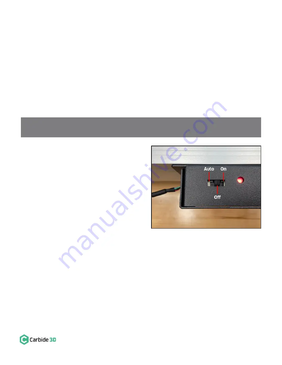
Power Switch Options 

The BitRunner power switch has three (3) positions 
(see 

Figure 8

):  

1.


Left (Forward): Auto On/Off, the LED is green 
or red. The G-code (or absence thereof) 
determines when BitRunner cuts or supplies 
power to the router. If there is no G-code/.nc 
file being executed in Carbide Motion, then no 
power is supplied to the router. When G-code 
is being executed in Carbide Motion, the 
commands will determine if power is on or off. 

a.


An M3 S command of 1000 or greater 
(1000 is the RPM) automatically turns 
the router on. M3 S2800 is an example M3 S command. Alternately, you might see commands 
written like this: M3S2800.  

b.


An M5 command turns the router off. 

c.


An M6 command indicates a tool change. 

2.


Middle: Always Off, the LED is red. Power is cut to the router. 

3.


Right (Rear): Always On, the LED is green. Power is supplied to the router. 


Figure 8 

NOTE:

 If you 

experience any problems with your BitRunner, don’t worry, we’ve got you covered! Just send an 

email to us at: 

[email protected]


and we’ll get you taken care of ASAP.


Содержание BitRunner

Страница 1: ...Kit Item Description Qty Note A BitRunner 1 BitRunner enclosure and attached power cords B Communications Cable 1 Gray 6 pin male to female extension cable C Mounting Hardware 2 M6 x 12mm button head...

Страница 2: ...t carbide3d com and we will get you back on track Install the BitRunner Attach BitRunner to Y2 Rail Newer Models With Z Plus The BitRunner attaches to the two M6 holes on the outside of the Y2 rail wi...

Страница 3: ...unting holes is 6 10 155mm 3 Use a 5mm drill bit for the tap hole and an M6 tap to form the threads Be sure to drill all the way through the outer wall of the extrusion and into the cavity 4 Use a 4mm...

Страница 4: ...rail 5 Use an SAE 3 32 inch hex key to remove the four 4 socket head cap screws in the corners of the Carbide Motion board The Carbide Motion board is taped to the enclosure and will need to be gentl...

Страница 5: ...board enclosure to the Y1 rail with the USB and power ports at the BACK and the 6 pin BitRunner connector at the FRONT 6 Reconnect the three 3 homing proximity switch cables and four 4 stepper motor e...

Страница 6: ...e an SAE 3 32 inch hex key and the four 4 existing socket head cap screws to secure the modified Carbide Motion board to the enclosure 4 Use a 4mm hex key and two 2 M6x12mm button head cap screws to a...

Страница 7: ...rom the Y2 rail See Figure 6 Make sure the plug is fully seated You will hear the latch click into place Connect the Female End to the Carbide Motion Board The FEMALE end of the communications cable c...

Страница 8: ...1 Left Forward Auto On Off the LED is green or red The G code or absence thereof determines when BitRunner cuts or supplies power to the router If there is no G code nc file being executed in Carbide...

Страница 9: ...d M6 Carbide Motion will pause the job cut power to the router and alert you that it s time to change the tool 2 For safety flip the power switch on the router to the OFF position and slide the power...

Отзывы: