docs.carbide3d.com
05/01/20
v1.1
5
2.
Peel the backing from the new tape on
the back of the new Carbide Motion
board.
3.
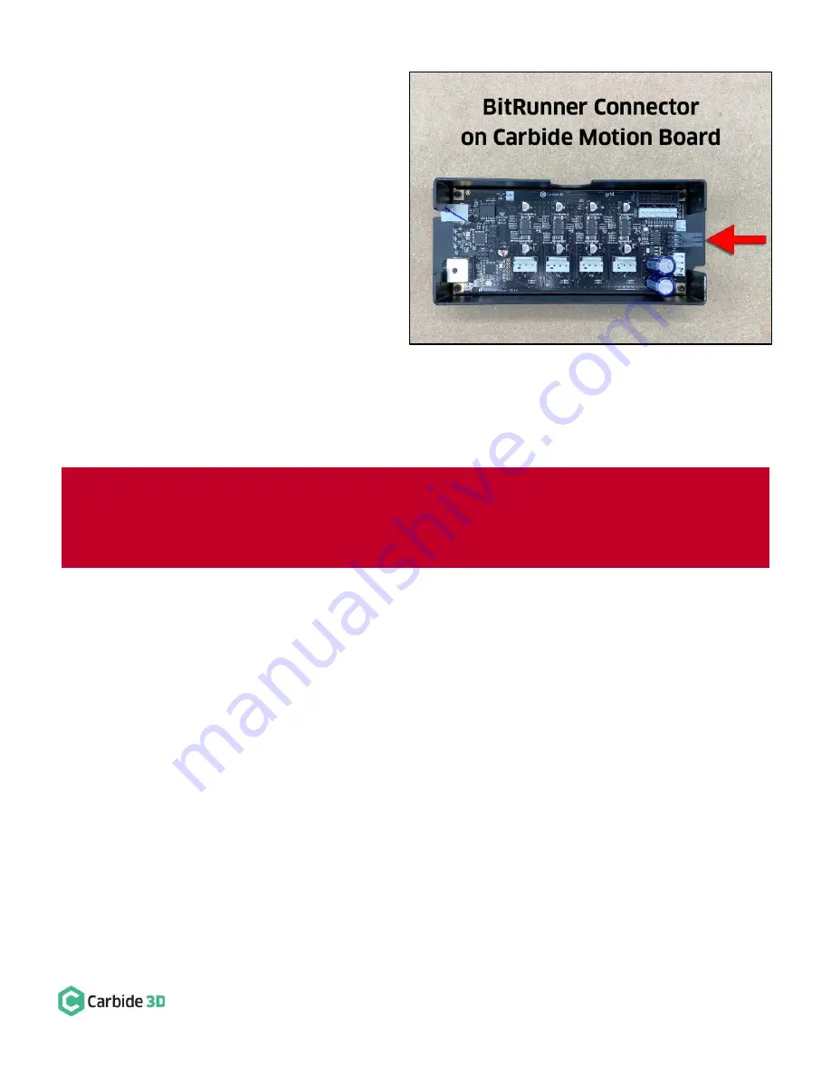
Insert the USB/power end of the board
into the enclosure first. The USB and
power ports will slightly protrude from
the BACK (left) of the enclosure. The
6-pin BitRunner connector protrudes
from the FRONT (right). See
Figure 4
.
4.
Use an SAE
3
/
32
-inch hex key and the four
(4) existing socket head cap screws to
secure the new Carbide motion board to
the enclosure.
5.
Use a 4mm hex key and two (2)
M6x12mm button head cap screws to
attach the Carbide Motion board enclosure to the Y1-rail with the USB and power ports at the BACK
and the 6-pin BitRunner connector at the FRONT.
6.
Reconnect the three (3) homing/proximity switch cables and four (4) stepper motor extension cables.
7.
Install the new enclosure cover included in the BitRunner kit and secure with existing hardware.
8.
Reconnect the power and USB cables at the rear of the Carbide Motion board.
Figure 4
WARNING:
The new 6-pin BitRunner connector protrudes from the front of the Carbide Motion board
enclosure. When installing the new cover, place it carefully over the BitRunner connector first, then bring it
down over the USB and power ports. If you should ever need to remove the cover, pry it open from the
USB/p
ower end first, then open like a book to avoid damaging the Bitrunner
connector.


