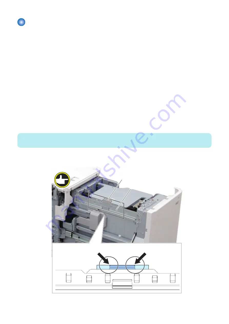
Pickup Assembly
■ Actions at Replacement
“Removing the Pickup Assembly” on page 42
■ Actions after Replacement
● Pre-Separation Plate Adjustment
1. Remove all sheets of paper from the Compartment and close the Compartment.
2. Turn ON the main power.
3. ( When the imageRUNNER ADVANCE C4500 series connected.)Execute the following item on the service mode.
• (Lv.1) COPIER> FUNCTION> CST> DK1-INT1( Initialization at Deck parts replacement)
4. Execute the following item on the service mode. Stop at pickup position
• (Lv.1) COPIER> FUNCTION> CST> DK1-SPAD(Setting of Deck Lifter stop position)
<Setting value>
0 to 1
0:Stop at lower limit position
1:Stop at pickup position
NOTE:
Even DK1-SPAD is set to 1, the value is returned to 0 when the Compartment is opened.
5. Check that the position between the Pre-Separation Plate and the Lifter Plate is same. Adjust it on the following
procedure in case that it is not same.
[2]
[1]
5. Adjustment
64
Содержание Paper Deck Unit-F1
Страница 13: ... Rear 1 2 No Name 1 Rear Cover 2 Right Cover 1 Product Overview 7 ...
Страница 14: ... Internal 1 2 3 No Name 1 Rear Edge Guide Plate 2 Lifter 3 Left right Edge Guide Plates 1 Product Overview 8 ...
Страница 17: ...Technology 2 Basic Configuration 12 Controls 16 ...
Страница 25: ...Few PS6 PS11 PS5 OFF ON ON Lifter Full PS6 PS11 PS5 ON ON ON Lifter 2 Technology 19 ...
Страница 29: ...Periodical Service 3 List of Work for Scheduled Servicing 24 ...
Страница 33: ...Parts List External Covers 1 2 3 4 5 4 Disassembly Assembly 27 ...
Страница 53: ...2 Remove the Deck Pickup Release Solenoid 1 2 Screws 2 2x 1 2 4 Disassembly Assembly 47 ...
Страница 67: ...Adjustment 5 Adjustment 62 Actions when Replacing the Parts 63 Other Adjustment 72 ...
Страница 73: ...8 Fasten the 2 screws 1 on the left loosened at procedure 2x 1 5 Adjustment 67 ...
Страница 75: ...10 Fasten the 2 screws on the right loosened at procedure 2x 1 5 Adjustment 69 ...
Страница 110: ...APPENDICES Service Tools 105 General Circuit Diagram 106 ...


