Chapter 2
2-29
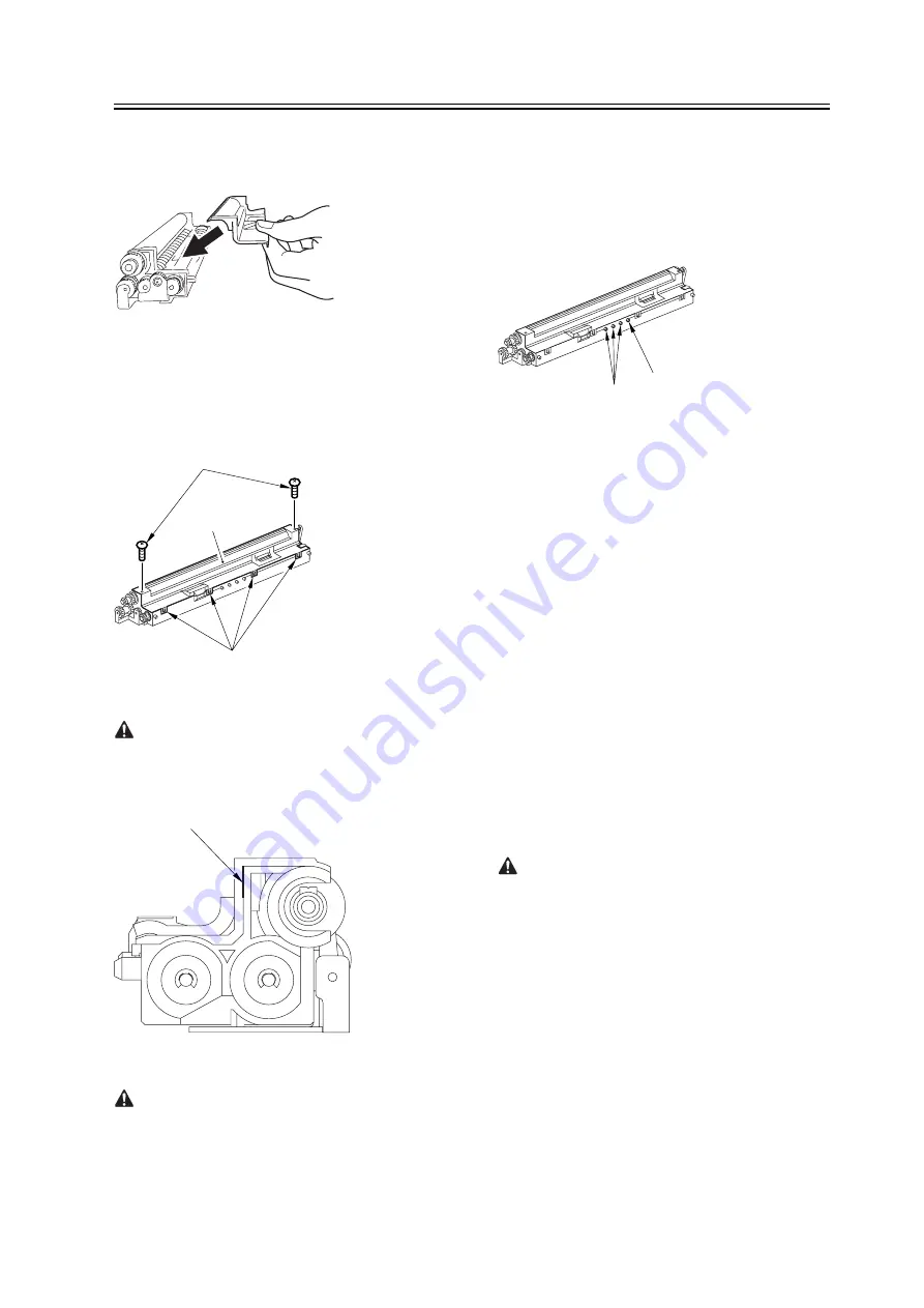
10) Fit the container lid you removed in step 2) back
on in the direction indicated in the figure.
F-2-35
Thereafter, engage the 4 hooks [1]; then, fix the
container lid [3] in place using the 2 screws [2] you
removed in step 3).
F-2-36
Force down the lid against the container so that the
gap [1] indicated in the figure is small enough to
prevent insertion of a transparency.
F-2-37
When tightening the screw, take full care so that
no shavings caused by turning the screw into the lid of
the developing assembly and the container will move
into the container.
11) Cut off the appropriate tab [1]] to suit the color of
the starter you have supplied. The tab A in the figure
is an extra tab.
F-2-38
12) Fit the color developing unit by going through the
steps used to detach it but in reverse.
13) Turn on the main power switch.
14) Make the following selections in service mode,
and set '1', and press the OK key:
COPIER>FUNCTION>INSTALL>AINR-OFF.
15) Select one of the following service mode items to
suit the color of the starter you have supplied; then,
press the OK key.
- if for the Y developing assembly,
COPIER>FUNCTION>INSTALL>INISET-Y
- if for the M developing assembly,
COPIER>FUNCTION>INSTALL>INISET-M
- if for the C developing assembly,
COPIER>FUNCTION>INSTALL>INISET-C
- if for the CMY developing assemblies,
COPIER>FUNCTION>INSTALL>INISET-3
A countdown is shown on the screen while this
mode item is under way. At the end, the screen will
show "OK!".
This mode uses ATVC control, possibly taking a
while depending on the site environment. The count
on the screen, for this reason, may loop between 690
and 620.
16) Execute the following service mode item:
COPIER>FUNCTION>MISC-P>P-PRINT. Store
away the generated printout in the service book case.
(If there is a previous printout, dispose of it.)
17) End service mode, and start user mode; on the
[3]
[1]
[2]
[1]
[A]
[1]
Содержание iR C6800 Series
Страница 1: ...Jan 20 2005 Portable Manual iR C6800 Series ...
Страница 2: ......
Страница 6: ......
Страница 12: ......
Страница 13: ...Chapter 1 Maintenance and Inspection ...
Страница 14: ......
Страница 16: ......
Страница 20: ...Chapter 1 1 4 Under high humidity and high temperature condition 85 000 images ...
Страница 51: ...Chapter 2 Standards and Adjustments ...
Страница 52: ......
Страница 79: ...F 2 27 1 ...
Страница 99: ...F 2 88 F 2 89 1 OK NG NG ...
Страница 110: ......
Страница 111: ...Chapter 3 Error Code ...
Страница 112: ......
Страница 114: ......
Страница 172: ......
Страница 173: ...Chapter 4 User Mode Items ...
Страница 174: ......
Страница 176: ......
Страница 188: ...LIPS emulation 12 items utility printer initialize yes no Item Description ...
Страница 190: ......
Страница 191: ...Chapter 5 Service Mode ...
Страница 192: ......
Страница 380: ......
Страница 381: ...Chapter 6 Outline of Components ...
Страница 382: ......
Страница 384: ......
Страница 387: ...F 6 1 SL7 CL3 CL2 SL6 SL8 SL9 SL2 SL1 SL4 SL3 SL5 CL1 SL10 SL11 SL12 ...
Страница 393: ...F 6 3 M19 M32 M31 M30 M17 M14 M29 M6 M9 M10 M11 M12 M25 M13 M28 M20 M22 M21 M26 M27 M15 M2 M5 M4 M3 M8 M1 M18 M23 ...
Страница 397: ...F 6 5 FM2 FM10 FM11 FM12 FM6 FM3 FM4 FM8 FM9 FM5 FM7 FM1 ...
Страница 407: ...F 6 9 PS65 PS38 PS39 PS46 PS44 PS45 PS52 PS53 PS58 PS59 PS37 ...
Страница 413: ...LA1 J602 601 J206 Notation Main controller PCB Inverter PCB Reader controller PCB AC driver PCB DC controller PCB ...
Страница 417: ...F 6 13 13 2 5 3 14 15 16 9 6 12 7 1 11 4 25 24 21 23 19 20 31 29 28 27 26 22 18 17 32 30 10 8 ...
Страница 418: ......
Страница 419: ...Chapter 7 System Construction ...
Страница 420: ......
Страница 422: ......
Страница 443: ...Chapter 8 Upgrading ...
Страница 444: ......
Страница 446: ......
Страница 455: ...Jan 20 2005 ...
Страница 456: ......


