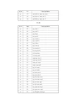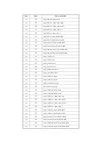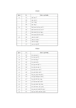
LGSW-
DSP
Use it to enable/disable indication of 'log display on/off' on the User
Mode screen.
2
Settings
0: do not indicate 'log display on/off'.
1: indicate 'log display on/off'
at time of shipment/upon RAM initialization: 0
PCL-
COPY
Use it to set the PCL command COPIES (Meru/Pinatubo/Hood
compatibility mode).
2
Setting mode
0: control page by page according to COPIES command setting on pages
1: Meru/Pinatubo/Hood compatible mode
2 to 65535: space
at time of shipment/upon RAM initialization: 0
PRJOB-
CP
Use it to set the CCV count pulse for reception/report output.
2
Settings
0: do not generate count pulse
1: generate count pulse
at time of shipment/upon RAM initialization: 0
DPT-ID-
7
Registering a department ID and inputting a 7-digit code for
authentication.
2
Setting Values
0: As before
[Initial setting upon shipment/value after RAM clear]
1: Inputting a 7-digit code
Reference Information
Support for Siemens
RUI-
RJT
Disconnecting the HTTP port when three authentication failures from
RUI are recognized.
2
Setting Values
0: Invalid
[Initial setting upon shipment/value after RAM clear]
1: Valid
Reference Information
Support for Siemens
COPIER>OPTION>USER
Subheadi
ng
Contents
Level
Содержание iR C6800 Series
Страница 1: ...Jan 20 2005 Portable Manual iR C6800 Series ...
Страница 2: ......
Страница 6: ......
Страница 12: ......
Страница 13: ...Chapter 1 Maintenance and Inspection ...
Страница 14: ......
Страница 16: ......
Страница 20: ...Chapter 1 1 4 Under high humidity and high temperature condition 85 000 images ...
Страница 51: ...Chapter 2 Standards and Adjustments ...
Страница 52: ......
Страница 79: ...F 2 27 1 ...
Страница 99: ...F 2 88 F 2 89 1 OK NG NG ...
Страница 110: ......
Страница 111: ...Chapter 3 Error Code ...
Страница 112: ......
Страница 114: ......
Страница 172: ......
Страница 173: ...Chapter 4 User Mode Items ...
Страница 174: ......
Страница 176: ......
Страница 188: ...LIPS emulation 12 items utility printer initialize yes no Item Description ...
Страница 190: ......
Страница 191: ...Chapter 5 Service Mode ...
Страница 192: ......
Страница 380: ......
Страница 381: ...Chapter 6 Outline of Components ...
Страница 382: ......
Страница 384: ......
Страница 387: ...F 6 1 SL7 CL3 CL2 SL6 SL8 SL9 SL2 SL1 SL4 SL3 SL5 CL1 SL10 SL11 SL12 ...
Страница 393: ...F 6 3 M19 M32 M31 M30 M17 M14 M29 M6 M9 M10 M11 M12 M25 M13 M28 M20 M22 M21 M26 M27 M15 M2 M5 M4 M3 M8 M1 M18 M23 ...
Страница 397: ...F 6 5 FM2 FM10 FM11 FM12 FM6 FM3 FM4 FM8 FM9 FM5 FM7 FM1 ...
Страница 407: ...F 6 9 PS65 PS38 PS39 PS46 PS44 PS45 PS52 PS53 PS58 PS59 PS37 ...
Страница 413: ...LA1 J602 601 J206 Notation Main controller PCB Inverter PCB Reader controller PCB AC driver PCB DC controller PCB ...
Страница 417: ...F 6 13 13 2 5 3 14 15 16 9 6 12 7 1 11 4 25 24 21 23 19 20 31 29 28 27 26 22 18 17 32 30 10 8 ...
Страница 418: ......
Страница 419: ...Chapter 7 System Construction ...
Страница 420: ......
Страница 422: ......
Страница 443: ...Chapter 8 Upgrading ...
Страница 444: ......
Страница 446: ......
Страница 455: ...Jan 20 2005 ...
Страница 456: ......


