Chapter 2
2-5
F-2-4
2.1.5
Image Adjustment Basic Procedure 5
0005-4339
iR C6800C / iR C6800CN / iR 5800C / iR 5800CN
Image Adjustment Basic Procedure 5
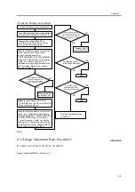
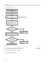
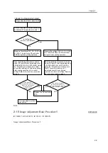
<Check the Developing output>
YES
YES
NO
NO
Color
Bk
Image adjustment basic procedure 4
Turn on the potential control mechanism:
COPIER>OPTION>BODY>P0-CNT '1'
Is the fault in
a color or in the black?
Measure the voltage DEV_DC_CONT at
J1132A-11 found on the DC controller
PCB during black printing operation.
Make the following selections in service
mode (DC level of black developing bias):
COPIER>DISPLAY>HV-STS>BIAS. Using
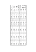
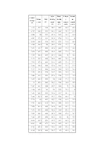
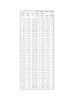
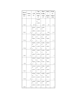
the "Potential control Conversion Table,"
convert the reading (in V) indicated during
black printing operation into a control
voltage. Refer to the result as conversion
value D.
Is the difference
between the actual measurement
of DEV-DC-CNT and the
foregoing value D
/-10%?
Replace the DC controller
PCB.
To image adjustment basic
procedure 5
Measure the voltage DEV_CL_DC_CONT
at J1132A-9 found on the DC controller
during full color printing operation.
Make the following selections in service
mode (DC level of color developing bias)
: COPIER>DISPLAY>HV-STS>BIAS.
Using the "Potential control Conversion
Table," convert the reading (in V)
indicated during full color printing
operation into a control voltage. Refer to
the result as conversion value C.
Is the difference between
the actual measurement of
DEV-DC-CNT and the foregoing
value C /-10%?
Содержание iR C6800 Series
Страница 1: ...Jan 20 2005 Portable Manual iR C6800 Series ...
Страница 2: ......
Страница 6: ......
Страница 12: ......
Страница 13: ...Chapter 1 Maintenance and Inspection ...
Страница 14: ......
Страница 16: ......
Страница 20: ...Chapter 1 1 4 Under high humidity and high temperature condition 85 000 images ...
Страница 51: ...Chapter 2 Standards and Adjustments ...
Страница 52: ......
Страница 79: ...F 2 27 1 ...
Страница 99: ...F 2 88 F 2 89 1 OK NG NG ...
Страница 110: ......
Страница 111: ...Chapter 3 Error Code ...
Страница 112: ......
Страница 114: ......
Страница 172: ......
Страница 173: ...Chapter 4 User Mode Items ...
Страница 174: ......
Страница 176: ......
Страница 188: ...LIPS emulation 12 items utility printer initialize yes no Item Description ...
Страница 190: ......
Страница 191: ...Chapter 5 Service Mode ...
Страница 192: ......
Страница 380: ......
Страница 381: ...Chapter 6 Outline of Components ...
Страница 382: ......
Страница 384: ......
Страница 387: ...F 6 1 SL7 CL3 CL2 SL6 SL8 SL9 SL2 SL1 SL4 SL3 SL5 CL1 SL10 SL11 SL12 ...
Страница 393: ...F 6 3 M19 M32 M31 M30 M17 M14 M29 M6 M9 M10 M11 M12 M25 M13 M28 M20 M22 M21 M26 M27 M15 M2 M5 M4 M3 M8 M1 M18 M23 ...
Страница 397: ...F 6 5 FM2 FM10 FM11 FM12 FM6 FM3 FM4 FM8 FM9 FM5 FM7 FM1 ...
Страница 407: ...F 6 9 PS65 PS38 PS39 PS46 PS44 PS45 PS52 PS53 PS58 PS59 PS37 ...
Страница 413: ...LA1 J602 601 J206 Notation Main controller PCB Inverter PCB Reader controller PCB AC driver PCB DC controller PCB ...
Страница 417: ...F 6 13 13 2 5 3 14 15 16 9 6 12 7 1 11 4 25 24 21 23 19 20 31 29 28 27 26 22 18 17 32 30 10 8 ...
Страница 418: ......
Страница 419: ...Chapter 7 System Construction ...
Страница 420: ......
Страница 422: ......
Страница 443: ...Chapter 8 Upgrading ...
Страница 444: ......
Страница 446: ......
Страница 455: ...Jan 20 2005 ...
Страница 456: ......


