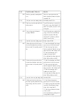
xx11
For INIT control (service mode
INISET-*) at time of initial setup, the
Ref value is lower than 62.
The ATR sensor is damaged or has an
open circuit. The connector may have
poor contact. The intermediate transfer
belt may be soiled>
Turn off and then on the main power;
then, execute the intermediate transfer
belt.
xx12
For INIT control (service mode
INISET-*) at time of initial setup, the
Sig value is 960 or higher.
The ATR sensor is damaged or has an
open circuit. The connector has poor
contact. The opening/closing of the
shutter is faulty. The intermediate
transfer belt is soiled.
Turn off and then on the main power;
then, execute the intermediate transfer
belt.
xx13
For INIT control (service mode
INISET-*) at time of initial setup, the
Ref value is 960 or higher.
The ATR sensor is damaged or has an
open circuit. The connector has poor
contact. The intermediate transfer belt
is soiled.
Turn off and then on the main power;
then, execute the intermediate transfer
belt.
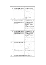
xx81
When the background (intermediate
transfer belt) is read during patch
detection, the P_base_adj value is
lower than 255.
The ATR sensor is damaged or has an
open circuit. The connector has poor
contact. The ITB cleaner is faulty.
Turn off and then on the main power;
then, execute the intermediate transfer
belt.
xx90
The result (Sig D) of computation
based on the reading of the patch during
patch detection (analog)) is lower than
16.
Turn off and then on the main power;
then, execute the intermediate transfer
belt.
xx91
The result (Sig D) of computation
based on the reading of the patch during
patch detection (analog) is 1008 or
higher.
The patch sensor is damaged or has an
open circuit. The connector has poor
contact. The primary transfer pressure
is faulty. The mounting of the
developing assembly is faulty.
Turn off and then on the main power;
then, execute the intermediate transfer
belt.
Code
Cause/Particulars of detection
Remarks
Содержание iR C6800 Series
Страница 1: ...Jan 20 2005 Portable Manual iR C6800 Series ...
Страница 2: ......
Страница 6: ......
Страница 12: ......
Страница 13: ...Chapter 1 Maintenance and Inspection ...
Страница 14: ......
Страница 16: ......
Страница 20: ...Chapter 1 1 4 Under high humidity and high temperature condition 85 000 images ...
Страница 51: ...Chapter 2 Standards and Adjustments ...
Страница 52: ......
Страница 79: ...F 2 27 1 ...
Страница 99: ...F 2 88 F 2 89 1 OK NG NG ...
Страница 110: ......
Страница 111: ...Chapter 3 Error Code ...
Страница 112: ......
Страница 114: ......
Страница 172: ......
Страница 173: ...Chapter 4 User Mode Items ...
Страница 174: ......
Страница 176: ......
Страница 188: ...LIPS emulation 12 items utility printer initialize yes no Item Description ...
Страница 190: ......
Страница 191: ...Chapter 5 Service Mode ...
Страница 192: ......
Страница 380: ......
Страница 381: ...Chapter 6 Outline of Components ...
Страница 382: ......
Страница 384: ......
Страница 387: ...F 6 1 SL7 CL3 CL2 SL6 SL8 SL9 SL2 SL1 SL4 SL3 SL5 CL1 SL10 SL11 SL12 ...
Страница 393: ...F 6 3 M19 M32 M31 M30 M17 M14 M29 M6 M9 M10 M11 M12 M25 M13 M28 M20 M22 M21 M26 M27 M15 M2 M5 M4 M3 M8 M1 M18 M23 ...
Страница 397: ...F 6 5 FM2 FM10 FM11 FM12 FM6 FM3 FM4 FM8 FM9 FM5 FM7 FM1 ...
Страница 407: ...F 6 9 PS65 PS38 PS39 PS46 PS44 PS45 PS52 PS53 PS58 PS59 PS37 ...
Страница 413: ...LA1 J602 601 J206 Notation Main controller PCB Inverter PCB Reader controller PCB AC driver PCB DC controller PCB ...
Страница 417: ...F 6 13 13 2 5 3 14 15 16 9 6 12 7 1 11 4 25 24 21 23 19 20 31 29 28 27 26 22 18 17 32 30 10 8 ...
Страница 418: ......
Страница 419: ...Chapter 7 System Construction ...
Страница 420: ......
Страница 422: ......
Страница 443: ...Chapter 8 Upgrading ...
Страница 444: ......
Страница 446: ......
Страница 455: ...Jan 20 2005 ...
Страница 456: ......


