


Startup System Failure Diagnosis
The viewpoint of this Startup System Failure Diagnosis
The goal of the startup system failure diagnosis is to be able to solve troubles associated with a Control Panel display failure by
performing the following steps.
It is assumed that the users have already learned the following items:
• How to use a tester
• Roles of the Low-voltage Power Supply (3.3V, 12V)(Power supply)
• How to back up data (HDD and Flash PCB)
CAUTION:
AC power supply is always supplied to the Low-voltage Power Supply PCB. Pay attention not to cause short circuit when
accessing the PCB.
■ Useful Operations
The items of detailed procedure explanation start with a description of the flow diagram. The items and procedures checked in
the flow diagram are described separately in a check item table. The flow diagram contains numbers (e.g. (1)) corresponding to
the check items so that the readers can grasp the relevant parts of the check item table.
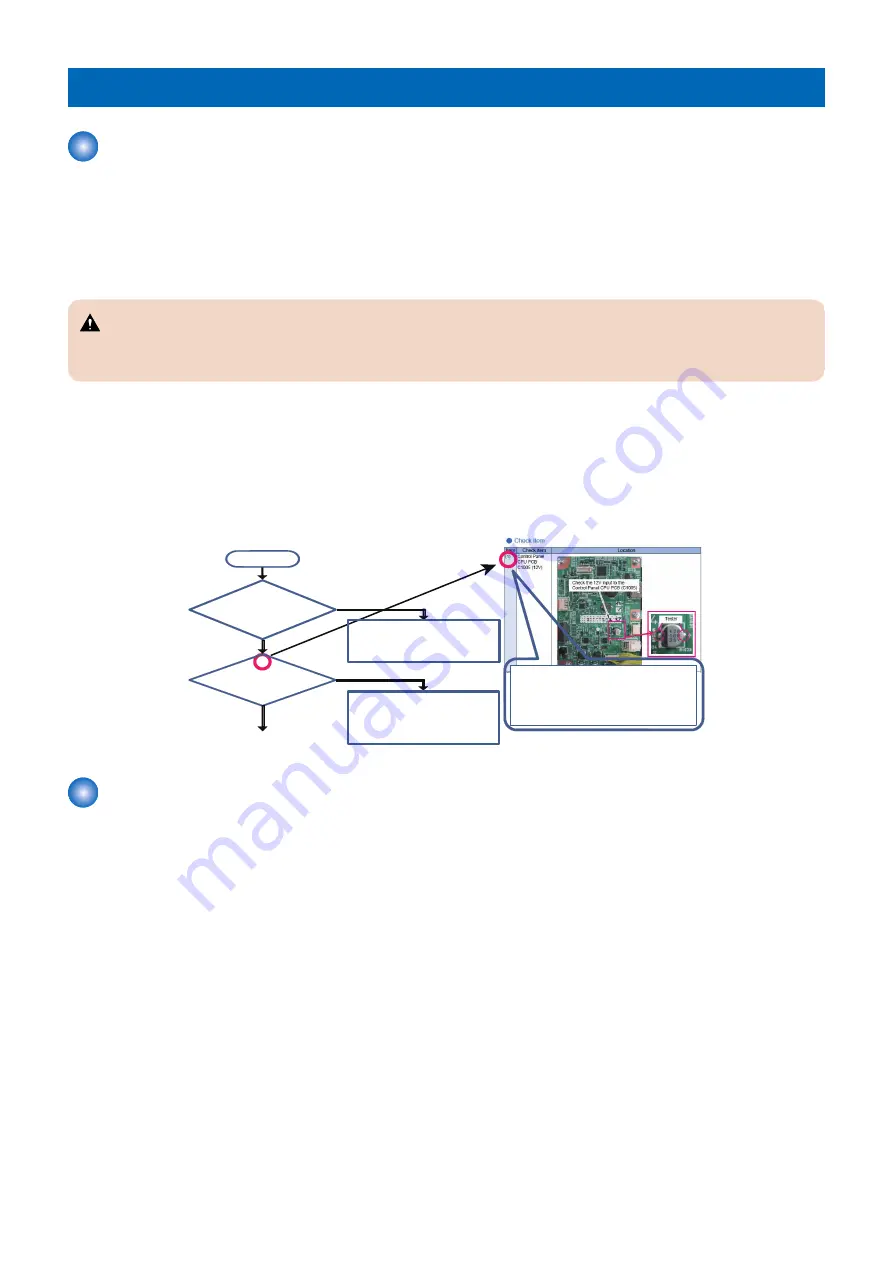
Flow
㻯㼔㼑㼏㼗㻌㼕㼠㼑㼙㻌㼘㼕㼟㼠
The location of each check item
can be referenced by the
corresponding number in the flow
diagram.
Has only
the backlight gone off?
(Can you hear the operation sound
of the Hard Key?)
Is 12V supplied to
C1005 of the Control Panel
CPU PCB?
Start
[Assumed failure location]
1. Control Panel CPU PCB
2. Main Controller PCB1
3. 12V Connector of the Control Panel
4. Control Panel Unit
No
Yes
Yes
[Assumed failure location]
1. Control Panel Unit
2. 12V Connector of the Control Panel
3. Main Controller PCB1
No
㻔㻝㻕
㻔㻞㻕
㻔㻟㻕
㻔㻞㻕
Startup Failure Analysis Policy
Startup Failure Analysis Policy describes troubleshooting related to "Execution Flow for Control Panel Startup Failure" for the
Low-voltage Power Supply (3.3V, 12V) and Low-voltage Power Supply PCB.
If the host machine does not start successfully even when its Power Switch is turned ON, identify the location of the failure by
referencing the following diagram.
Select the appropriate failure location identification procedure based on the display status of the Control Panel.
Preconditions
If the following two parts are not operating with the main power turned ON, it is likely that a failure has occurred.
• Control Panel Main Power LED (Low-voltage Power Supply 3.3V system)
• Rotation noise of the motor at warm-up rotation and activation of the Control Panel Backlight (12V system)
6. Troubleshooting
417
Содержание imageRUNNER ADVANCE C3320 Series
Страница 1: ...Revision 7 0 imageRUNNER ADVANCE C3330 C3325 C3320 Series Service Manual ...
Страница 18: ...Product Overview 1 Product Lineup 7 Features 11 Specifications 17 Parts Name 26 ...
Страница 278: ...J1335 J1066 J1022 J1146 J1050 J1051 J130 J1052 J1053 J1333 J120 J128 J130 4 Parts Replacement and Cleaning 266 ...
Страница 326: ...CAUTION Check that the color of the seal at the center is black 4 Parts Replacement and Cleaning 314 ...
Страница 359: ...6 Remove the Bottle Drive Unit 1 2 Bosses 2 5 Hooks 3 2 2 3 3 3 2 2 1 3 3 3 3 4 Parts Replacement and Cleaning 347 ...
Страница 399: ...Adjustment 5 Pickup Feed System 388 Document Exposure System 391 Actions after Replacement 393 ...
Страница 518: ...Error Jam Alarm 7 Overview 507 Error Code 511 Jam Code 617 Alarm Code 624 ...
Страница 1020: ...9 Installation 1008 ...
Страница 1022: ...2 Perform steps 3 to 5 in each cassette 9 Installation 1010 ...
Страница 1024: ...5 6 Checking the Contents Cassette Feeding Unit 1x 3x 2x 1x 9 Installation 1012 ...
Страница 1027: ...3 4 NOTE The removed cover will be used in step 6 5 2x 2x 9 Installation 1015 ...
Страница 1046: ...When the Kit Is Not Used 1 2 Close the Cassette 2 When the Kit Is Used 1 9 Installation 1034 ...
Страница 1058: ...3 4 CAUTION Be sure that the Inner 2 way Tray Support Member is installed properly 9 Installation 1046 ...
Страница 1062: ...Installation procedure 1 NOTE The work is the same when the Utility Tray is installed 9 Installation 1050 ...
Страница 1068: ... Removing the Covers 1 2x 2 1x 9 Installation 1056 ...
Страница 1070: ...3 1x 1x 9 Installation 1058 ...
Страница 1080: ...Installation Outline Drawing Installation Procedure 1 Remove the all tapes from this equipment 2 2x 9 Installation 1068 ...
Страница 1081: ...3 CAUTION To avoid damage do not pull the A part of the Utility Tray too much A 4 9 Installation 1069 ...
Страница 1083: ...6 7 TP M4x8 2x 2x 9 Installation 1071 ...
Страница 1084: ...When Installing the USB Keyboard 1 Cap Cover Wire Saddle 9 Installation 1072 ...
Страница 1095: ...9 2x 10 2x 11 Remove the Face Seals from the Reader Right Cover The removed Face Seals will not be used 9 Installation 1083 ...
Страница 1101: ... When Stopping to Use 1 Press Reset key or the Voice Recognition button for more than 3 seconds 9 Installation 1089 ...
Страница 1129: ...9 2x 10 2x 11 9 Installation 1117 ...
Страница 1135: ...Remove the covers 1 ws 2x 2 1x 9 Installation 1123 ...
Страница 1140: ...2 2x 3 Connect the power plug to the outlet 4 Turn ON the power switch 9 Installation 1128 ...
Страница 1155: ...Installation Outline Drawing Installation Procedure Removing the Covers 1 2x 2 1x 9 Installation 1143 ...
Страница 1157: ...3 Connect Power Cable and Signal Cable disconnected in the step 2 to the Encryption Board 2 Connectors 2x 9 Installation 1145 ...
Страница 1167: ...Installation Procedure Removing the Covers 1 2x 2 1x 3 2x Installing the Removable HDD Kit 9 Installation 1155 ...
Страница 1176: ... A 2x Installing the Covers 1 1x 2 2x 9 Installation 1164 ...
Страница 1177: ...3 4 2x Installing the Removable HDD 1 Install the HDD Unit to the HDD Slot 9 Installation 1165 ...
Страница 1182: ...Installation Outline Drawing Installation Procedure Removing the Covers 1 2x 2 1x 9 Installation 1170 ...
Страница 1190: ...14 Install the Cable Guide to the HDD Frame 4 Hooks 1 Boss 9 Installation 1178 ...
Страница 1195: ...23 Secure the Power Cable in place using the Wire Saddle 1x Installing the Covers 1 1x 2 2x 9 Installation 1183 ...
Страница 1196: ...3 4 2x Installing the Removable HDD 1 Install the HDD Unit to the HDD Slot 9 Installation 1184 ...


