


Part 5: Maintenance
BJC-5000
5-31
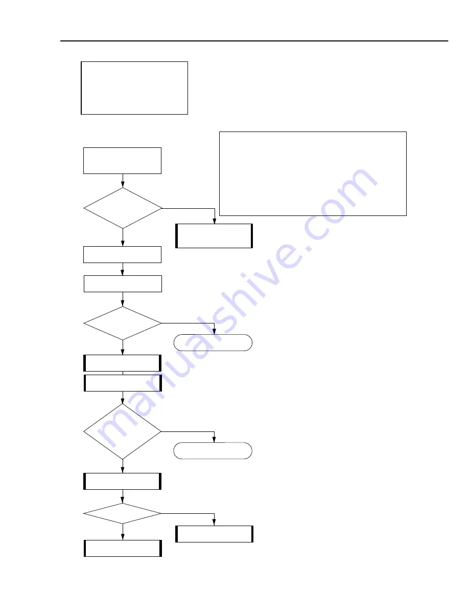
<Symptom>
• There is blotching.
• There are white stripes on the printed paper.
• There are certain dots not printed.
<Cause>
• The BJ cartridge or cartridge contacts is/are faulty.
• The carriage cable is faulty.
• The purge unit is faulty.
<Corrective Actions>
Troubleshooting consists of error condition
diagnosis, which is required if the cause of an error
is unknown, and error recovery, which is performed
if the cause of an error is known. If the cause of
an error is unknown, perform the error condition
diagnosis, and if it is known, perform error
recovery.
White stripe sample
Yes
No
Check the
environment and
paper specifications.
Yes
No
END
1. Replace the ink
cartridge.
2. Replace the BJ
cartridge.
Do they
meet the required
specifications ?
Use paper which
meets the
specifications.
Remove and re-install
the BJ cartridge.
Execute a test print.
Is the
printing result
defective ?
Yes
No
END
Check the carriage
cable conductivity.
Yes
No
Conduction
cutoff ?
Replace the
carriage unit.
Replace the
purge unit.
Do
blotches and/or
stripes still appear on the
printed paper even
after cartridge
replacement ?
While the printer is turned on, hold down
the
POWER button
for one beep.
Then release the
POWER button
to print out the test pattern.
4.Faulty Printing
<2>: Stripes
Appear
Содержание Color Bubble Jet BJC-5000 Series
Страница 2: ...0898 SC 0 55 0 ...
Страница 3: ......
Страница 14: ......
Страница 28: ......
Страница 48: ...Part 2 Product Specifications BJC 5000 2 20 This page intentionally left blank ...
Страница 50: ......
Страница 72: ......
Страница 116: ...Part 4 Technical Reference 4 44 BJC 5000 This page intentionally left blank ...
Страница 118: ......
Страница 160: ......
Страница 161: ...The printing paper contains 70 waste paper PRINTED IN JAPAN IMPRIME AU JAPON CANON INC ...


