ENGLISH
Page
26
- Manual code:
FA00464-EN
ver
.
1
03/2017 © C
AME S.p.a. - The data and information shown in this manual ar
e t
o be consider
ed as subject t
o change at any time and without the need for any advance warning.
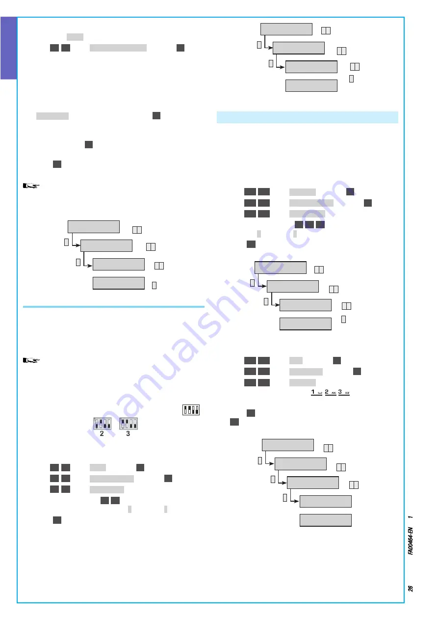
STEP 2: Addressing reader
1 Stay in the
SYSTEM
menu
2 With
(
▲
)
/
(
▼
)
select
INSERTERS ADDRESSING
and press
(*)
3 The address of the reader not found on the bus, which needs
to be addressed, appears on the display
4 Approach a key (even one that has not been acquired) to the
reader to which you want to assign the address shown on the
display and wait until the LEDs flash slowly and the buzzer
sounds
5
INSERTER 02 OK
appears on the keypad Press
(*)
to continue
6 If there are other readers to be addressed the procedure
will start again from the beginning When they have all been
learned, pressing
(*)
lets you see that all the readers are con-
nected and assigned an address
7 Press
(#)
to quit and go back to the previous menus
Through the technical menu of the on-board keypad it is also
possible to locally record common messages, messages associated
with areas, scenarios, outputs, inputs, keys and codes
*
*
SYSTEM 02
ADDRESSING
INSERTERS
▼
▲
▼
▲
ON INSERTER 02
APPROACH KEY
▼
▲
INSERTER OK
PRESS */OK
*
ACQUIRING RADIO RECEIVER MODULES ON BUS
The control unit's factory settings include radio receiver 1 enabled,
which corresponds to the local receiver
In order to connect another radio receiver module on a Bus, given
that they are all produced with the address 01, their address must
be changed, making it 02 or 03
The system cannot have radio receiver modules on the bus
with identical addresses
STEP 1: Address the expansion
1 On the expansion module set the address that you want to as-
sign, using the 4 microswitches (Example address 3:
O
N
1
)
2 STEP 2: Enabling radio receiver on bus
3 Go into the Technical Menu
4 With
(
▲
)
/
(
▼
)
select
SYSTEM
and press
(*)
5 With
(
▲
)
/
(
▼
)
select
MODIFY SYSTEM
and press
(*)
6 With
(
▲
)
/
(
▼
)
select
RADIO MODULES
7 Press the number key
(2)
/
(3)
relating to the address of the
expansion module to be enabled (
#
= enabled,
-
disabled)
8 Press
(#)
to quit and go back to the previous menus
9 The communication LED on the module bus will start to flash
*
▼
▲
▼
▲
▼
▲
*
3
SYSTEM 02
MODIFY
SYSTEM
RADIO MODULES
--
RADIO MODULES
#-
Defining system areas
The areas are integral parts of the system and must therefore be
defined during the programming stage
Defining the areas is useful for managing the "totally on" status
even when using only three areas
STEP 1: Enabling areas
1 Go into the Technical Menu
2 With
(▲)
/
(▼)
select
SYSTEM 02
and press
(*)
3 With
(▲)
/
(▼)
select
MODIFY SYSTEM
and press
(*)
4 With
(▲)
/
(▼)
select
MANAGED AREAS
5 Press the number key
(1)
/
(2)
/
(3)
relating to the area to be
enabled (
#
= enabled,
-
= disabled)
6 Press
(#)
to quit and go back to the previous menus
*
*
SYSTEM 02
MODIFY
SYSTEM
▼
▲
▼
▲
MANAGED AREAS
##-
▼
▲
MANAGED AREAS
###
3
STEP 2: Edit area description
1 Staying in the Technical Menu
2 With
(▲)
/
(▼)
select
AREAS
and press
(*)
3 With
(▲)
/
(▼)
select
MODIFY AREA 01
and press
(*)
4 With
(▲)
/
(▼)
select
DESCRIPTION
5 With the alphanumeric keys
you can edit the
text
6 Press
(#)
to confirm and go back to the previous menus Press
(#)
to cancel the change
*
*
*
AREAS 04
MODIFY AREA 01
AREA 01
▼
▲
▼
▲
DESCRIPTION 01
AREA 01
▼
▲
AREA 01
*=OK #=ESC
LIVING AREA
*=OK #=ESC


