iL Series User Manual
California Instruments
Rev B
21
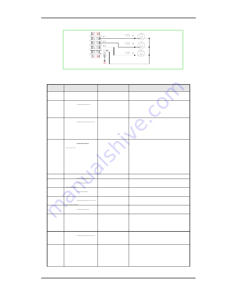
Figure 10 Verification Connections
Step
Procedure
Display
Explanation
1.
Turn the unit on.
Meter mode
Meter mode is active and the
Dis
annunciator should be on.
2.
Press Voltage
key
VOLT 0.00
Display indicates the default
settings. If you are verifying a
three phase source, all phase
annunciators should be on.
3.
Press 1 2 0 Enter
VOLT 120
Programs the output on 1 to 120
volts. After the value is entered,
the display returns to Meter mode,
which indicates that no voltage is
applied to the output.
4.
Press Output
on/off
120 V 60 HZ
Turns the output on and applies
120 volts to the 1 light bulb. The
Dis
annunciator should be off and
CV
should be on. Repeat steps 3
and 4 for phase 2 and phase 3 of
three phase sources. All three
light bulbs should be lit when this
action is complete.
5.
Press Voltage
VOLT 120
6.
Press Phase
Select
VOLT 120
Select until all phase annunciators
are lit on three phase source.
7.
Press 0 Enter
VOLT 0
Turns off all light bulbs connected
to the source.
8.
Press Voltage 1 2
0 Enter
VOLT 120
Turns on all light bulbs connected
to the source.
9.
Press Protect
PROT:CLEAR
Display accesses the protection
menu list.
10.
Press
s
or
t
and scroll to the
VOLT:PROT
item.
VOLT:PROT
500
Display shows the overvoltage
protection trip voltage for your
unit.
11.
Press 1 0 0 Enter
VOLT:PROT
100
Programs the OVP to 100 volts,
which is less than the previously
set output voltage.
0 V 60 HZ
Because the OVP voltage entered
was less than the output voltage,
the OVP circuit tripped. The
output dropped to zero,
CV
turned
off, and
Prot
turned on.
Содержание 3000iL
Страница 9: ...iL Series User Manual California Instruments Rev B ix page intentionally left blank...
Страница 10: ......
Страница 37: ...iL Series User Manual California Instruments Rev B 27...
Страница 84: ...iL Series User Manual 74 Rev B California Instruments Figure 21 Troubleshooting Diagram for No Output Present...
Страница 89: ...iL Series User Manual California Instruments Rev B 79 Figure 23 AC Power Source Block Diagram...
Страница 93: ...iL Series User Manual California Instruments Rev B 83 Figure 25 AC Input Board Parts Location...
Страница 94: ...iL Series User Manual 84 Rev B California Instruments Figure 26 Mother Board Parts Location...


