Configuring Frame Relay
7-17
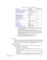
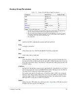
If an RS-232 DCE port is directly connected to the DTE via the standard
Cabletron cable, the maximum supported speed is 64K. If longer cabling is
used, the maximum speed is 19.2K. (The EIA standard for RS-232
addresses speeds up to 19.2 Kbps.)
Maximum Bytes per Frame
specifies the maximum size of any I-frame (Information frame) that can be transmitted
or received on the port.
Logical DCE
defines the port as (if
Y
) logical DCE or (if
N
) DTE. The port must be configured as
the opposite of the device at the other end of the connection.
Logical and physical DCE/DTE are independent of each other (e.g., a port can be a
physical DCE and logical DTE).
Generate Clock
specifies whether the port will generate the clock necessary to synchronize traffic over
the link. If the port is a physical DCE (determined by the port's I/O cable interface),
set this parameter to
Y
, since the physical DCE generates clock. If the port is DTE, set
the parameter to
N
.
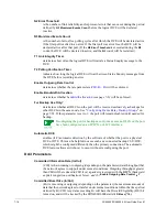
Rcv Clock (TT) from DTE
allows the clock to be looped back from the DTE using the TT (Terminal Timing)
signal, which can be helpful on high-speed lines. Generally, if the local interface is
physical DCE and the line speed is above 256 Kbps, this parameter should be set to
Y
.
(Make sure the remote DTE is configured to provide the terminal timing.)
CSU/DSU Operating Mode
determines whether the attached modem connection can be normal or limited distance
(LDM), where the distance depends on the wire gauge, number of splice points, and
line speed. For example, 26-gauge wire and a line speed of 64K bps allows a distance
of 15000 feet. Lowering the speed to 56K increases the allowable distance to 18000
feet. If 19-gauge wire is used, the distances can be multiplied by three.
RTS Control
if configured as
Constant
means that RTS (Request to Send) will always be asserted;
if configured as
External,
the CSU/DSU will control RTS.
Link Layer Management
determines whether, and what type of, configurable network management (e.g., status
enquiries to the port) will be used: none, LMI (Local Management Interface), or ANSI
T1.617 Annex D (an ANSI-standard LMI).
N1 Polling Count
specifies the number of polling cycles between requests for Full Status reports, which
include status of all PVCs on the physical link. Every "
T1
" seconds (see "
T1 Link
Integrity Timer
" on page 7-18), the logical DTE will send a Status Enquiry to the
network, requesting status of the network link. Each exchange of one enquiry and one
message (response) is a polling cycle. After every "
N1
" cycles, an enquiry for a Full
Status report will be sent.
If this port is configured as logical DCE, status enquiries will be initiated at the DTE,
and the local node will respond with status messages.
Содержание Netlink FRX4000
Страница 2: ......
Страница 16: ...xiv FRX4000 FRX6000 4 0 User Guide Rev 01 ...
Страница 17: ...Section I Getting Started ...
Страница 18: ......
Страница 24: ......
Страница 37: ...Section II Configuration ...
Страница 38: ......
Страница 52: ......
Страница 78: ......
Страница 106: ...7 24 FRX4000 FRX6000 4 0 User Guide Rev 01 ...
Страница 142: ...8 36 FRX4000 FRX6000 4 0 User Guide Rev 01 ...
Страница 186: ......
Страница 216: ......
Страница 266: ......
Страница 273: ...Section III Operation ...
Страница 274: ......
Страница 296: ......
Страница 324: ......
Страница 376: ......
Страница 377: ...Section IV Appendices ...
Страница 378: ......
Страница 384: ......
Страница 390: ......
Страница 396: ......
Страница 400: ......
Страница 405: ...Menu Structure E 5 ...
Страница 406: ...E 6 FRX4000 FRX6000 4 0 User Guide Rev 01 ...
Страница 425: ......
Страница 426: ......


