C-TEC QT601-2 Скачать руководство пользователя страница 32

QT601-2 Quantec Controller

General Note

Quantec systems should be installed using Network Splitters. These pre-commissioning instructions are based on their use for the
following reasons:

•        They ensure voltage drop problems are substantially avoided.
•        They blow a fuse and keep most of the system working if a network limb is shorted.
•        They allow cable and equipment faults to be easily found and isolated.
•        They allow the system to be connected a section at a time, avoiding problems with other trades initialising devices out of sequence.

Using other wiring schemes may work, but installation errors will be more difficult to detect and voltage drop may be a problem.
Do not megger the wiring with ANY devices connected.

Pre-Commissioning

The installing contractor should carry out the following tests so that the commissioning engineer can get the system operating
quickly. If these are not done, commissioning may be refused or extra charges made.

Things you will need:

Quantec Main instructions (this document) available from your Installer or C-TEC 

;  Individual instructions supplied with each

device 

;  Terminal screwdriver 

; 5 mm flat blade screwdriver 

; 3 mm Allen key 

 

; Side cutters 

; Wire strippers 

; Digital

multimeter 

.

Things you will be expected to have done:

1.      All spine wiring from the Quantec Controller to the network splitters should be in place, checked & certified correct.
2.      All limb wiring from the network splitters to network devices should be in place, checked & certified correct.
3.      The spine and limb cables should be left connected to the splitters.
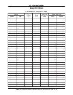
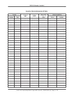
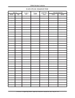
4.      All limb wiring should be labelled so you know which devices are connected to where. Use the Splitter Connection Chart 

         (located at the back of this document).

5.      All room wiring to ceiling pulls, overdoor lights and slave call points (if fitted) should be in place, checked & certified correct.

Checking the Spine Wiring

•       Power up the Quantec Controller. A number of messages will flash quickly on the Controller’s LCD display before the
         words ‘QUANTEC’ and the time in hours and minutes appear constantly (please note, the time shown may not be correct).
•       Do not connect batteries. Look at the green power lights on the network splitters.
•       If none are lit, check the spine voltage at the Quantec Controller – you should see a changing reading in the range of 16 to
         17 volts DC. If the voltage is much lower, disconnect the spine and check the voltage again. If the reading jumps up, you 
         have a wiring fault. If you fix this fault and the reading still remains low, you may have another wiring fault. If you suspect
         the Quantec Controller may be faulty, disconnect the spine wiring at the Controller and check the voltage at the Quantec
         Controller with no wires connected. If the voltage is okay (i.e. within the range 16 to 17 volts DC) you still have wiring faults.
•       A short on the spine will not blow a fuse but nothing will work except the display on the Quantec Controller.
•       If any one splitter is not lit, it is probably not connected or the wiring to it is shorted.
•       Sort out any wiring problems and repeat the tests until all green lights are lit on the splitters.

Checking the Limb Wiring

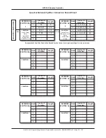
•       Go to a network splitter and connect one limb at a time, carrying out the following tests.
•       If any fault lights are lit, check the fuses at that splitter. The limb connected to a blown fuse is probably short circuit. Fix 
         the fault and replace the fuse (always fit 400 mA 20 mm quick blow fuses). Note that, if the limb wires are very long, it is 
         possible that a short will not blow a fuse. However, the fault can be found by disconnecting limbs in turn (when the short 
         circuit limb is disconnected the network should spring into life).

Appendix 7 - Pre-Commissioning Instructions

Installation & Programming Manual • Approved Document No. DNU6012001 Rev 5 • Page 32 of 42

Содержание QT601-2

Страница 1: ...QT601 2 QUANTEC CONTROLLER installation and programming manual Approved Document No DNU6012001 Rev 5...

Страница 2: ...s 28 Appendix 4 Auxiliary Outputs 28 Appendix 5 Quantec Paging Functionality 29 Appendix 6 Wiring for Addressable Call Points Ceiling Receivers 30 31 Appendix 7 Pre Commissioning Instructions 32 34 Ap...

Страница 3: ...the system as a whole The manufacturer s policy is one of continuous improvement and we reserve the right to make changes to product specifications at our discretion and without prior notice E OE Whe...

Страница 4: ...infrared call points ceiling receivers and radio receivers Ideal for use in individual bedrooms or communal areas such as lounges where they eliminate the need for long and potentially hazardous tail...

Страница 5: ...ing devices 10 17 are assigned as members of one Area Area A and all Displays in West Wing devices 2 and 3 are assigned as members of one Group Group 1 A similar scenario applies to the East Wing the...

Страница 6: ...TABLE Call Point AREA Display GROUP Addressable Overdoor Light ZONE Max no of Addressable Devices 255 Max no of Areas 26 Max no of Groups 32 Max no of Zones 64 D Display Z Addressable Overdoor Light o...

Страница 7: ...Zonal Routing Tables are located at the back of this document Quantec ZONAL ROUTING TABLE max 8 Areas Devices per equation Example Requirement 4 Although standard patient and HELP REQUIRED calls shoul...

Страница 8: ...needs to be given to how they will interact until system programming Slave devices such as slave ceiling pulls slave overdoor lights and slave infrared ceiling receivers connect to Quantec via a mast...

Страница 9: ...der 3 3 2 2 3 If slave overdoor lights are fitted in corridors good practice is to loop the network in and out of the overdoor lights and then spur off into the relevant addressable call point inside...

Страница 10: ...to each network splitter General Purpose Wiring Instructions With Quantec a limiting factor is voltage drop which should be limited to 5 volts worse case As call points and overdoor lights take differ...

Страница 11: ...Lights are not used Spine Length Calculator Use the Spine Length Calculator below to work out the maximum spine cable lengths taking into account the number and type of devices connected to any networ...

Страница 12: ...pillars taking care not to damage any of the components The Controller s lid and base PCBs can now be removed to prevent accidental damage Note The base PCBs are static sensitive and relevant anti sta...

Страница 13: ...llows the installer to power the system without connecting the mains supply For this to work two fully charged 12 V VRLA batteries should be connected in series as shown below always ensure correct po...

Страница 14: ...s site specific data PCB retaining screw must be secured tightly before operation Lid Base connecting cable connects to PL1 on Front Panel Display and Switch PCB VR1 Volume Pot turn to increase or dec...

Страница 15: ...that a particular device is programmed as anticipated A handy way of doing this is to program a Display and then press the A button which will display its ID number Whilst the autoassign function is a...

Страница 16: ...2 6 2 7 2 8 2 9 2 10 2 11 2 12 2 13 2 14 1 1 1 2 1 3 1 4 1 5 1 6 1 7 1 7 1 8 2 15 2 16 2 17 1 9 1 10 4 1 4 2 4 3 4 4 4 7 4 5 4 6 Pager Mode Pager Level DECT Protocol Auto Reset Mode Auto Reset Time Pr...

Страница 17: ...V Room EW01 When the final character has been accepted the Assign New Device prompt reappears Note Exiting this option before the final character has been accepted will cancel the description change 1...

Страница 18: ...it Custom Texts function described in section 1 7 On pressing the Accept button your choice will be confirmed e g By using the scroll and Accept keys four single alphanumeric characters can now be tag...

Страница 19: ...1 use the scroll keys to highlight Div and press Accept This equation describes where calls from the selected Group should be diverted to if a call has not been accepted before a pre determined time...

Страница 20: ...essage will appear When the sending process is complete the Controller will automatically return to the Assignment Menu The renamed custom text fields will now be available to the appropriate device n...

Страница 21: ...t Code This option allows Quantec s four digit Call Reset code to be entered or changed this can be any combination of the scroll up scroll down and Accept keys On selecting the Set Call Reset prompt...

Страница 22: ...ALL levels of call accepting this enables paging on RESET and ALL levels of call It should be noted that different levels of calls are not prioritised by pagers For example if a STANDARD call is trig...

Страница 23: ...and its confidence LED will be lit or in the case of an addressable overdoor light or sounder its beeper will be sounding at the STANDARD call rate If the state field 0 OK the device has been found by...

Страница 24: ...Display IDs prompt the following two options are available This function if set to Enabled sends Caller ID details to the Quantec Displays when a call is presented on the system with the information...

Страница 25: ...Please note this function will only work if the Controller s datalogger has been programmed to print manually refer to section 2 6 and a printer is properly connected to its RS232 printing port 4 3 Se...

Страница 26: ...1 Stop Bit No Parity Display Parameters Note When there are concurrent Normal calls from Call Points and Monitor Points the Monitor Point Call Rate is used Call Point Parameters Addressable Overdoor...

Страница 27: ...set 1 10 9 02am Lounge 2 Attack 1 10 9 02am Lounge 2 Reset 1 10 10 15am Bedroom G F 4 Call 1 10 10 15am Bedroom G F 4 Emergency 1 10 10 18am Bedroom G F 4 Presence 1 10 10 18am Bedroom G F 4 Reset Fau...

Страница 28: ...Appendix 4 Auxiliary Outputs Seven auxiliary outputs are provided at the Quantec Controller as listed below The outputs can be used for driving peripheral equipment as per the following examples Exam...

Страница 29: ...r only looks for the ACK once it has sent the ENQ it doesn t respond to any other data sent to it The Message embodies the paging message itself alert tone and message checksum and is assembled as fol...

Страница 30: ...NNECTOR PLK1 For optional special programming functions requires QT423A adaptor L L A C LK3 P K4 L P Short to give the QT302RX an ID when in assignment mode once assigned these pins can be used to mak...

Страница 31: ...t Max 3 slave call points or ceiling pulls any mix connected in parallel per master call point QT423 CONFIG CONNECTOR PLK1 For optional special programming functions requires QT423A adaptor QT607 CEIL...

Страница 32: ...fitted should be in place checked certified correct Checking the Spine Wiring Power up the Quantec Controller A number of messages will flash quickly on the Controller s LCD display before the words Q...

Страница 33: ...ently is backlit and shows the unassigned message This means that the display has been installed correctly If the display shows the time it is assigned and should be reset using the reset ID pins see...

Страница 34: ...belled Yes No SIGNED _______________________________________ DATE ____________________________________________ CONTRACTORS NAME ________________________________________________________________________...

Страница 35: ...ce voltage drop No of limbs per splitter 6 Max cable length per limb 60 m Max no of addressable devices per limb 15 Max no of addressable devices per system 255 Network voltage 24 V nominal Network ma...

Страница 36: ...ation Programming Manual Approved Document No DNU6012001 Rev 5 Page 36 of 42 DEVICE Call Point AREA Display GROUP Addressable Overdoor Light ZONE PLACE DESCRIPTION Number Type Name Number Quantec Devi...

Страница 37: ...Installation Programming Manual Approved Document No DNU6012001 Rev 5 Page 37 of 42 DEVICE Call Point AREA Display GROUP Addressable Overdoor Light ZONE PLACE DESCRIPTION Number Type Name Number Quant...

Страница 38: ...Installation Programming Manual Approved Document No DNU6012001 Rev 5 Page 38 of 42 DEVICE Call Point AREA Display GROUP Addressable Overdoor Light ZONE PLACE DESCRIPTION Number Type Name Number Quant...

Страница 39: ...tec Controller Installation Programming Manual Approved Document No DNU6012001 Rev 5 Page 39 of 42 Quantec Group Routing Table max 8 Areas Groups per equation GROUP PRIMARY AREAS NIGHT AREAS BEEP DIVE...

Страница 40: ...01 2 Quantec Controller Quantec Zonal Routing Table max 8 Areas Devices per equation ZONE AREA EQUATION DEVICE EQUATION Installation Programming Manual Approved Document No DNU6012001 Rev 5 Page 40 of...

Страница 41: ...R No Limb Device ID Numbers Length 1 2 Location 3 4 5 6 QUANTEC CONTROLLER NETWORK SPLITTER No Limb Device ID Numbers Length 1 2 Location 3 4 5 6 NETWORK SPLITTER No Limb Device ID Numbers Length 1 2...

Страница 42: ...Device Replace Device Setup Group Setup Zone Edit Cust Texts Send Cust Texts Setup Divert Exit Menu ACCESS LEVEL 1 System Setup Set Assignment New Device Assignment Menu SystemSetupMenu Double Addres...

Отзывы: