C-TEC QT601-2 Скачать руководство пользователя страница 19

QT601-2 Quantec Controller

Installation & Programming Manual • Approved Document No. DNU6012001 Rev 5 • Page 19 of 42

1.5     Assigning or Editing Area/Group Relationships

In order to route Areas (calling devices) to relevant Groups
(Displays), routing equations must be programmed into the
Quantec  Controller.  Move  through  the  menus  to  the
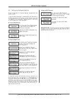
Assignment Menu and Accept the 'Setup Group' prompt. The
following prompt will be displayed:

To set up or change the primary (Day) equation for Group 1
use the scroll keys to highlight "Pri" and press Accept. This
equation  describes  to  which  Area(s)  of  calling  devices  the
Group of Displays will respond when Quantec is in day mode.
Depending  on  data  already  entered,  the  following  will
appear:

Use the scroll and Accept keys to enter the appropriate Area(s)
with reference to the 'Group Routing Table' on Page 39. Up
to eight Areas can be selected for a Group. All eight terms
must  be  accepted,  even  if  they  are  blank.  Pressing  Escape
before  this  process  is  complete  will  abort  editing  without
making changes. When the eighth term has been accepted
the ‘Select Group’ prompt will again be shown, e.g:

To set up or change the Night equation for Group 1 use the
scroll buttons to highlight "Nite" and press Accept.

When in night mode, Quantec routes all Areas to all Groups
but only the Display Groups that are programmed to beep in
the 'Night' mode will do so. Use the scroll and Accept keys to
enter the appropriate Area(s) with reference to the 'Group
Routing Table' on Page 39. All eight terms must be accepted,
even if they are blank as pressing Escape before this process
is complete will abort editing without making changes.

When the eighth term has been accepted the ‘Select Group’
prompt will appear again, e.g.

To set up or change the Divert equation for Group 1 use the
scroll keys to highlight "Div" and press Accept.

This equation describes where calls from the selected Group
should be diverted to if a call has not been accepted before a
pre-determined time has elapsed or manual divert has been
selected from a Display’s menu. By default, Divert equations
are  blank  (i.e.  divert  will  not  operate).  Use  the  scroll  and
Accept keys to enter the appropriate Area(s) with reference
to the 'Group Routing Table' on Page 39. All eight terms must
be accepted, even if they are blank. Pressing Escape before
this  process  is  complete  will  abort  editing  without  making
changes.

1.6     Setting up Addressable Overdoor Lights and 

          Addressable Sounders

To route a call to the relevant Addressable Overdoor Light(s)
or Sounder(s), Zone equations must be programmed into the
system. Move through the menus to the Assignment Menu
and Accept the 'Setup Zone' prompt. The following prompt
will appear:

Use  the  scroll  and  Accept  keys  to  enter  the  appropriate
Areas/Devices with reference to the 'Zonal Routing Table' on
Page 40. The Zone equation describes to which Areas and/or
devices the Zone will respond to in both primary (day) and
night mode.

Note

: Addressable overdoor lights and addressable sounders

can include both Areas and individual calling devices in their
routing equations. By default these equations are blank. This
means  addressable  overdoor  lights  and  sounders  will  not
function until their routing equations have been defined. A
maximum of eight Areas can be assigned to each Group. All
eight terms must be accepted, even if they are blank. Pressing
Escape  before  this  process  is  complete  will  abort  editing
without  making  changes.  In  night  mode,  Addressable
Overdoor Lights and Sounders are silent.

Select Group 001
Pri Nite Div ESC

Group 01 Pri Mode
A

Group 1 Displays default to Area A; Group 2 to Area
B, etc. These may be altered to suit the system.

Select Group 001
Pri Nite Div ESC

Select Group 001
Pri Nite Div ESC

Select Group 001
Areas / Devices

Содержание QT601-2

Страница 1: ...QT601 2 QUANTEC CONTROLLER installation and programming manual Approved Document No DNU6012001 Rev 5...

Страница 2: ...s 28 Appendix 4 Auxiliary Outputs 28 Appendix 5 Quantec Paging Functionality 29 Appendix 6 Wiring for Addressable Call Points Ceiling Receivers 30 31 Appendix 7 Pre Commissioning Instructions 32 34 Ap...

Страница 3: ...the system as a whole The manufacturer s policy is one of continuous improvement and we reserve the right to make changes to product specifications at our discretion and without prior notice E OE Whe...

Страница 4: ...infrared call points ceiling receivers and radio receivers Ideal for use in individual bedrooms or communal areas such as lounges where they eliminate the need for long and potentially hazardous tail...

Страница 5: ...ing devices 10 17 are assigned as members of one Area Area A and all Displays in West Wing devices 2 and 3 are assigned as members of one Group Group 1 A similar scenario applies to the East Wing the...

Страница 6: ...TABLE Call Point AREA Display GROUP Addressable Overdoor Light ZONE Max no of Addressable Devices 255 Max no of Areas 26 Max no of Groups 32 Max no of Zones 64 D Display Z Addressable Overdoor Light o...

Страница 7: ...Zonal Routing Tables are located at the back of this document Quantec ZONAL ROUTING TABLE max 8 Areas Devices per equation Example Requirement 4 Although standard patient and HELP REQUIRED calls shoul...

Страница 8: ...needs to be given to how they will interact until system programming Slave devices such as slave ceiling pulls slave overdoor lights and slave infrared ceiling receivers connect to Quantec via a mast...

Страница 9: ...der 3 3 2 2 3 If slave overdoor lights are fitted in corridors good practice is to loop the network in and out of the overdoor lights and then spur off into the relevant addressable call point inside...

Страница 10: ...to each network splitter General Purpose Wiring Instructions With Quantec a limiting factor is voltage drop which should be limited to 5 volts worse case As call points and overdoor lights take differ...

Страница 11: ...Lights are not used Spine Length Calculator Use the Spine Length Calculator below to work out the maximum spine cable lengths taking into account the number and type of devices connected to any networ...

Страница 12: ...pillars taking care not to damage any of the components The Controller s lid and base PCBs can now be removed to prevent accidental damage Note The base PCBs are static sensitive and relevant anti sta...

Страница 13: ...llows the installer to power the system without connecting the mains supply For this to work two fully charged 12 V VRLA batteries should be connected in series as shown below always ensure correct po...

Страница 14: ...s site specific data PCB retaining screw must be secured tightly before operation Lid Base connecting cable connects to PL1 on Front Panel Display and Switch PCB VR1 Volume Pot turn to increase or dec...

Страница 15: ...that a particular device is programmed as anticipated A handy way of doing this is to program a Display and then press the A button which will display its ID number Whilst the autoassign function is a...

Страница 16: ...2 6 2 7 2 8 2 9 2 10 2 11 2 12 2 13 2 14 1 1 1 2 1 3 1 4 1 5 1 6 1 7 1 7 1 8 2 15 2 16 2 17 1 9 1 10 4 1 4 2 4 3 4 4 4 7 4 5 4 6 Pager Mode Pager Level DECT Protocol Auto Reset Mode Auto Reset Time Pr...

Страница 17: ...V Room EW01 When the final character has been accepted the Assign New Device prompt reappears Note Exiting this option before the final character has been accepted will cancel the description change 1...

Страница 18: ...it Custom Texts function described in section 1 7 On pressing the Accept button your choice will be confirmed e g By using the scroll and Accept keys four single alphanumeric characters can now be tag...

Страница 19: ...1 use the scroll keys to highlight Div and press Accept This equation describes where calls from the selected Group should be diverted to if a call has not been accepted before a pre determined time...

Страница 20: ...essage will appear When the sending process is complete the Controller will automatically return to the Assignment Menu The renamed custom text fields will now be available to the appropriate device n...

Страница 21: ...t Code This option allows Quantec s four digit Call Reset code to be entered or changed this can be any combination of the scroll up scroll down and Accept keys On selecting the Set Call Reset prompt...

Страница 22: ...ALL levels of call accepting this enables paging on RESET and ALL levels of call It should be noted that different levels of calls are not prioritised by pagers For example if a STANDARD call is trig...

Страница 23: ...and its confidence LED will be lit or in the case of an addressable overdoor light or sounder its beeper will be sounding at the STANDARD call rate If the state field 0 OK the device has been found by...

Страница 24: ...Display IDs prompt the following two options are available This function if set to Enabled sends Caller ID details to the Quantec Displays when a call is presented on the system with the information...

Страница 25: ...Please note this function will only work if the Controller s datalogger has been programmed to print manually refer to section 2 6 and a printer is properly connected to its RS232 printing port 4 3 Se...

Страница 26: ...1 Stop Bit No Parity Display Parameters Note When there are concurrent Normal calls from Call Points and Monitor Points the Monitor Point Call Rate is used Call Point Parameters Addressable Overdoor...

Страница 27: ...set 1 10 9 02am Lounge 2 Attack 1 10 9 02am Lounge 2 Reset 1 10 10 15am Bedroom G F 4 Call 1 10 10 15am Bedroom G F 4 Emergency 1 10 10 18am Bedroom G F 4 Presence 1 10 10 18am Bedroom G F 4 Reset Fau...

Страница 28: ...Appendix 4 Auxiliary Outputs Seven auxiliary outputs are provided at the Quantec Controller as listed below The outputs can be used for driving peripheral equipment as per the following examples Exam...

Страница 29: ...r only looks for the ACK once it has sent the ENQ it doesn t respond to any other data sent to it The Message embodies the paging message itself alert tone and message checksum and is assembled as fol...

Страница 30: ...NNECTOR PLK1 For optional special programming functions requires QT423A adaptor L L A C LK3 P K4 L P Short to give the QT302RX an ID when in assignment mode once assigned these pins can be used to mak...

Страница 31: ...t Max 3 slave call points or ceiling pulls any mix connected in parallel per master call point QT423 CONFIG CONNECTOR PLK1 For optional special programming functions requires QT423A adaptor QT607 CEIL...

Страница 32: ...fitted should be in place checked certified correct Checking the Spine Wiring Power up the Quantec Controller A number of messages will flash quickly on the Controller s LCD display before the words Q...

Страница 33: ...ently is backlit and shows the unassigned message This means that the display has been installed correctly If the display shows the time it is assigned and should be reset using the reset ID pins see...

Страница 34: ...belled Yes No SIGNED _______________________________________ DATE ____________________________________________ CONTRACTORS NAME ________________________________________________________________________...

Страница 35: ...ce voltage drop No of limbs per splitter 6 Max cable length per limb 60 m Max no of addressable devices per limb 15 Max no of addressable devices per system 255 Network voltage 24 V nominal Network ma...

Страница 36: ...ation Programming Manual Approved Document No DNU6012001 Rev 5 Page 36 of 42 DEVICE Call Point AREA Display GROUP Addressable Overdoor Light ZONE PLACE DESCRIPTION Number Type Name Number Quantec Devi...

Страница 37: ...Installation Programming Manual Approved Document No DNU6012001 Rev 5 Page 37 of 42 DEVICE Call Point AREA Display GROUP Addressable Overdoor Light ZONE PLACE DESCRIPTION Number Type Name Number Quant...

Страница 38: ...Installation Programming Manual Approved Document No DNU6012001 Rev 5 Page 38 of 42 DEVICE Call Point AREA Display GROUP Addressable Overdoor Light ZONE PLACE DESCRIPTION Number Type Name Number Quant...

Страница 39: ...tec Controller Installation Programming Manual Approved Document No DNU6012001 Rev 5 Page 39 of 42 Quantec Group Routing Table max 8 Areas Groups per equation GROUP PRIMARY AREAS NIGHT AREAS BEEP DIVE...

Страница 40: ...01 2 Quantec Controller Quantec Zonal Routing Table max 8 Areas Devices per equation ZONE AREA EQUATION DEVICE EQUATION Installation Programming Manual Approved Document No DNU6012001 Rev 5 Page 40 of...

Страница 41: ...R No Limb Device ID Numbers Length 1 2 Location 3 4 5 6 QUANTEC CONTROLLER NETWORK SPLITTER No Limb Device ID Numbers Length 1 2 Location 3 4 5 6 NETWORK SPLITTER No Limb Device ID Numbers Length 1 2...

Страница 42: ...Device Replace Device Setup Group Setup Zone Edit Cust Texts Send Cust Texts Setup Divert Exit Menu ACCESS LEVEL 1 System Setup Set Assignment New Device Assignment Menu SystemSetupMenu Double Addres...

Отзывы: