INSTRUCTION, USE AND
MAINTENANCE MANUAL
Page 17 of 36
GB
12.4 Wheel clamping on the mandrel
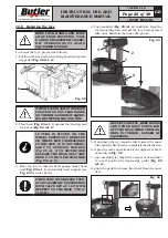
To block the wheel from inside:
1. Grease tyre edges with the grease contained in the
appropriate cup (see operating figure
Fig. 15
).
2. Release the hexagon shaft (
Fig. 15 ref. 2
) through
the relevant push-button on handle (
Fig. 15 ref. 1
)
and take it up, fully home. Control horizontal arm
(
Fig. 15 ref. 3
) tilting through the pedal.
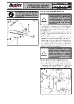
3. The wheel can be secured to the mandrel by placing
jaws either inside or outside the rim (see Chapter
15 “Technical specifications” for required rim size).
WHEN SECURING THE WHEEL DO
NOT KEEP HANDS UNDER THE
TYRE.
Make sure that the wheel is placed at the centre of
the self-centring table (
Fig. 15 ref. 6
). Make sure
the wheel is clamped by jaws (
Fig. 15 ref. 7
) sym-
metrically.
B) WHEEL SECURING OUTSIDE THE RIM
(for
allowed rim size, see Chapter 15 Technical speci-
fications)
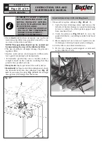
In order to carry out the clamping of the wheel from
the outside:
1. pressing pedal (
Fig. 15 ref. 9
) in intermediate posi-
tion, place the 4 fixing jaws (
Fig. 15 ref. 7
) at the
same level of the tyre diameter.
2. Place the wheel on the mandrel, press the rim down-
ward and completely lower pedal (
Fig. 15 ref. 9
)
to secure the wheel.
B) WHEEL SECURING (INSIDE THE RIM)
(for al-
lowed rim size, see Chapter 15. “Technical speci-
fications”)
To block the wheel from inside:
1. close preventively fixing jaws (
Fig. 15 ref. 7
), by
means of pedal (
Fig. 15 ref. 9
). Place the wheel on
the mandrel. Push down the rim while completing
lowering the pedal and releasing it. The jaws release,
thus securing the rim.
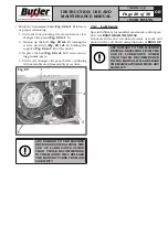
Fig. 15
7300-M023-0_B
HP441S.XX - HP441S.XXFI
HP441SQ.XX - HP441SQ.XXFI


