INSTRUCTION, USE AND
MAINTENANCE MANUAL
GB
Page 32 of 43
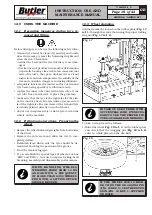
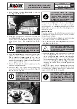
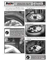
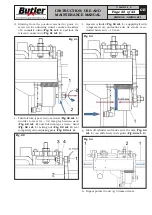
d. Starting from the position reached at point (c),
screw neck’s adjusting dowel counter-clockwise
of 2 complete turns (
Fig.
61 ref. 1
) and lock the
relevant counter nut (
Fig.
61 ref. 2
).
Fig. 61
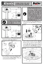
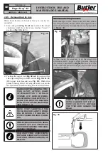
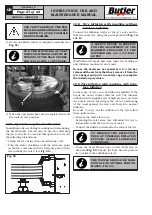
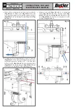
e. Turn fulcrum-type screw (or screws) (
Fig.
62 ref. 1
)
in order to reset 0.1 ÷ 0.2 mm play between neck
(
Fig.
62 ref. 2
) and fulcrum-type screws’ head
(
Fig.
62 ref. 1
), letting nut (
Fig.
62 ref. 3
) rest
completely onto adjusting plate (
Fig.
62 ref. 4
).
Fig. 62
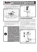
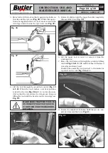
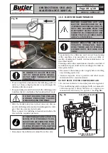
f. Operate cylinder (
Fig.
63 ref. 1
), supplying it with
compressed air, and make sure its stroke is in-
cluded between 5 ÷ 10 mm.
Fig. 63
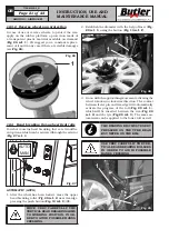
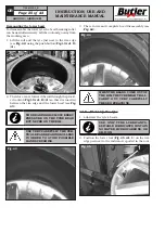
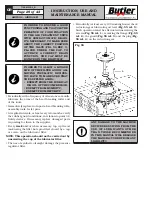
g. Blow off cylinder and make sure the arm (
Fig.
64
ref. 1
) can slide freely in its guide (
Fig.
64 ref. 2
).
Fig. 64
h. Repeat points (f) and (g) 3 times at least.
7104-M009-2_B
AIKIDO.4 - AIKIDO.4FI

