INSTRUCTION, USE AND
MAINTENANCE MANUAL
GB
Page 26 of 43
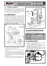
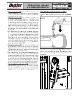
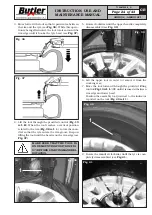
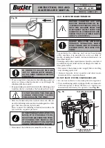
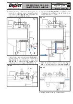
3. Hook the bead on the tool (
Fig.
46 ref. 1
) then ro-
tate in a clockwise direction until bead’s complete
assembly. Remove the lower tool from the working
area until the bead is completely released.
Fig.
46
1
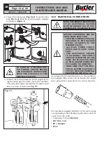
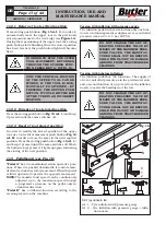
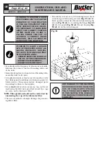
4. Position the upper tool (
Fig.
47 ref. 1
) just next to
the rim edge.
MAKE SURE PUSH BUTTON "1" OF
FIG.15 IS BACKLIGHTED BEFORE
PRESSING THE PUSH BUTTON TO
MOVE AUTOMATICALLY THE UP-
PER TOOL TO THE PREVIOUSLY
STORED POSITION (SEE CHAP.
11.2.1, RETURN FUNCTION).
Fig.
47
1
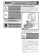
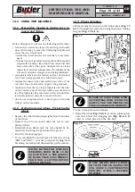
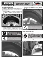
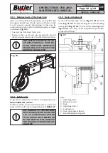
5. Then, position the upper bead on the tool assembly
area (
Fig.
48 ref. 1
).
Fig. 48
1
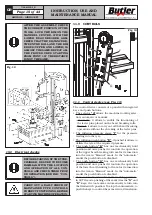
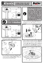
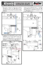
6. Assemble the extension with entrainer near the rim
edge (see
Fig.
49
).
Fig.
49
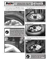
7. Lower the upper bead breaker roll so that the tyre
bead is kept at the same height of the rim groove
(see
Fig.
50
).
Fig.
50
THE BEADING DISC MUST EXERT
PRESSURE ON THE TYRE BEAD
BUT NEVER ON THE RIM.
7104-M009-2_B
AIKIDO.4 - AIKIDO.4FI

