INSTRUCTION, USE AND
MAINTENANCE MANUAL
GB
Page 19 of 43
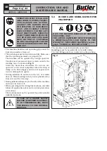
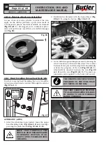
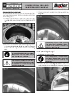
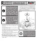
Fig. 19
FOR WHEELS WITH ALLOY RIMS,
USE THE PROPER PLASTIC GUARD
(FIG. 20 REF. 1).
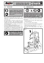
Fig. 20
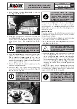
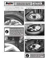
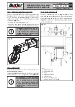
2. Remove the locking ring nut (
Fig. 21 ref. 1
) from
the activator support (
Fig. 21 ref. 2
).
Fig. 21
3. By removing the locking ring-nut (
Fig. 21 ref. 1
)
from the activator support (
Fig. 21 ref. 2
), the
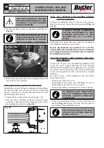
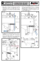
central threaded shaft (
Fig. 22 ref. 1
) lifts auto-
matically until its maximum height.
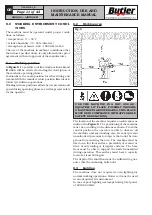
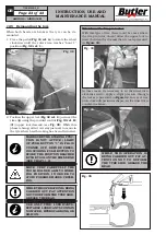
AFTER A DEFAULT MANUFACTUR-
ING TIME, THE THREADED SHAFT
(
Fig. 22 ref. 1
)
RETURNS TO ITS
OWN HOUSING. IF THE LOCKING
RING-NUT HAS NOT BEEN IN-
SERTED YET, IT IS POSSIBLE TO
MAKE IT COME OUT AGAIN, BY
ACTIVATING MANUALLY THE AC-
TIVATOR SUPPORT
(
Fig. 22 ref. 4
)
OR BY REPOSITIONING
(
Fig. 22
ref. 3
)
AND THEN, GRABBING THE
(
Fig. 22 ref. 5
)
LOCKING RING-
NUT FROM ITS OWN SUPPORT, AS
INDICATED IN FIG. 22.
4 - Insert and block the ring-nut (
Fig. 22 ref. 2
) on
the threaded shaft (
Fig. 22 ref. 1
) as described
hereafter.
Fig. 22
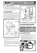
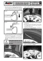
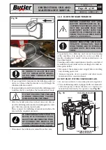
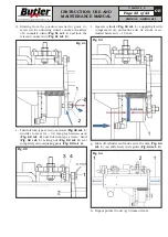
5 - Rotate clockwise the small internal levers (
Fig. 23A
ref. 1
), until they reach the outer levers (
Fig. 23A
ref. 2
) in order to unlock the ring-nut. Make the
rink-nut (
Fig. 23A ref. 3
) and the cone (
Fig. 23A
ref. 4
) approach the rim (
Fig. 23A ref. 5
). Release
the small inner levers (
Fig. 23A ref. 1
), the ring-nut
gets locked on the threaded shaft (
Fig. 23A ref. 6
).
Fig. 23A
7104-M009-2_B
AIKIDO.4 - AIKIDO.4FI

