72
n. Drain second quart sample from lower Gauge
Glass fitting. If sample is not clear, repeat cycle
of draining boiler and return main and refilling
boiler until sample is clear.
o. If after normal operation boiler water becomes
dirty from additional system piping sediment
returning to boiler.
i
. Complete steps 5a through 5n.
ii.
Complete steps 3a through 3k.
6. Make pH or Alkalinity Test.
a
.
After boiler and system have been cleaned and
refilled as previously described, test the pH of
the water in the system. This can easily be done
by drawing a small sample of boiler water and
testing with Hydrion paper which is used in the
same manner as litmus paper, except it gives
specific readings. A color chart on the side of the
small Hydrion dispenser gives the reading in pH.
Hydrion paper is inexpensive and obtainable
from any chemical supply house or through your
local druggist. The pH should be higher than 7
but lower than 11. Add recommended water
treatment chemicals, if necessary, to bring the pH
within the specified range. With this lower level
of protection, care must be exercised to eliminate
all of the free oxygen in the system.
b
.
Boiler is now ready to be put into service.
N.
Clean Heating System (Water).
A local qualified
water treatment chemical specialist is a suggested
source for recommendations regarding appropriate
chemical compounds and concentrations which are
compatible with local environmental regulations.
1. Boiling Out of Boiler and System. Oil and grease
which accumulate in a new hot water boiler can be
washed out in the following manner.
a
.
Remove Safety Relief Valve using extreme care
to avoid damaging it.
b
.
Partially fill boiler. Pour recommended
compound into boiler through safety relief valve
opening.
c
.
Replace Safety Relief Valve.
d
.
Fill entire system with water.
e
.
Start firing equipment.
f
.
Circulate the water through the entire system.
g
.
Vent the system, including the radiation.
h
.
Allow boiler water to reach operating
temperature, if possible.
i
.
Continue to Circulate the water for a few hours.
j
.
Stop the firing equipment.
k
.
Drain the system in a manner and to a location
that hot water can be discharged with safety.
l
.
Remove plugs from all available returns and
wash the water side of the boiler as thoroughly as
possible, using a high-pressure water stream.
m
.
Refill the system with fresh water.
n
.
Add recommended boiler water treatment.
2. Make pH or Alkalinity Test.
a
.
After boiler and system have been cleaned and
refilled as previously described, test the pH of
the water in the system. This can easily be done
by drawing a small sample of boiler water and
testing with Hydrion paper which is used in the
same manner as litmus paper, except it gives
specific readings. A color chart on the side of the
small Hydrion dispenser gives the reading in pH.
Hydrion paper is inexpensive and obtainable
from any chemical supply house or through your
local druggist. The pH should be higher than 7
but lower than 11. Add recommended water
treatment chemicals, if necessary, to bring the pH
within the specified range. With this lower level
of protection, care must be exercised to eliminate
all of the free oxygen in the system.
b
.
Boiler is now ready to be put into service.
CONDENSATION — Following a cold start,
condensation (sweating) may occur in a gas fired
boiler to such an extent that it appears that the boiler
is leaking. This condensation can be expected to
stop after the boiler is hot.
O.
Check Damper Operation
- If boiler is equipped with
vent damper, vent damper must be in open position
when boiler main burners are operating. Start boiler,
refer to instructions on damper to determine if damper
is in full open position.
P.
Review User's Information Manual
and system
operation with owner or operator.
Q.
Post instructions
near boiler for reference by owner
and service personnel. Maintain instructions in legible
condition.
Содержание Independence
Страница 4: ... Figure 1 Dimensional Drawing ...
Страница 19: ...19 Figure 25 Recommended Water Piping for Circulator Zoned Heating System ...
Страница 20: ...20 Figure 25A Recommended Water Piping for Zone Valve Zoned Heating System ...
Страница 29: ...29 Figure 34 Vent Damper Schematic Wiring Diagram Figure 33 Vent Damper Harness to Limit ...
Страница 30: ...30 Figure 35 Wiring Diagrams Steam Continuous Ignition Standing Pilot Probe Low Water Cutoff ...
Страница 32: ...32 Figure 36 Wiring Diagrams Steam Intermittent Ignition EI Probe Low Water Cutoff ...
Страница 34: ...34 Figure 37 Wiring Diagrams Steam Intermittent Ignition HSP Probe Low Water Cutoff ...
Страница 36: ...36 Figure 38 Wiring Diagrams Steam Continuous Ignition Standing Pilot Float Low Water Cutoff ...
Страница 38: ...38 Figure 39 Wiring Diagrams Steam Intermittent Ignition EI Float Low Water Cutoff ...
Страница 40: ...40 Figure 40 Wiring Diagrams Steam Intermittent Ignition HSP Float Low Water Cutoff ...
Страница 42: ...42 Figure 41 Wiring Diagrams Water Continuous Ignition Standing Pilot Intermittent Circulation ...
Страница 44: ...44 Figure 42 Wiring Diagrams Water Intermittent Ignition EI Intermittent Circulation ...
Страница 46: ...46 Figure 43 Wiring Diagrams Water Intermittent Ignition HSP Intermittent Circulation ...
Страница 48: ...48 Figure 44 Wiring Diagrams Water Continuous Ignition Standing Pilot Gravity Circulation ...
Страница 50: ...50 Figure 45 Wiring Diagrams Water Intermittent Ignition EI Gravity Circulation ...
Страница 52: ...52 Figure 46 Wiring Diagrams Water Intermittent Ignition HSP Gravity Circulation ...
Страница 54: ...54 Figure 47 Wiring Diagrams Water Continuous Ignition Standing Pilot Tankless Heater ...
Страница 56: ...56 Figure 48 Wiring Diagrams Water Intermittent Ignition EI Tankless Heater ...
Страница 58: ...58 Figure 49 Wiring Diagrams Water Intermittent Ignition HSP Tankless Heater ...
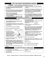
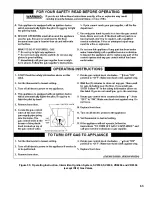
Страница 61: ...61 Figure 53 Lighting Instructions Continuous Ignition System VR8200 and VR8300 Gas Valves ...
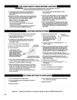
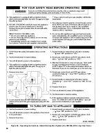
Страница 62: ...62 Figure 54 Lighting Instructions Continuous Ignition System 7000 ERHC Gas Valve ...
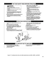
Страница 64: ...64 Figure 56 Operating Instructions Intermittent Ignition System EI VR8304 IN12 only Gas Valves ...
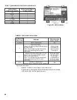
Страница 65: ...65 Figure 57 Operating Instructions Intermittent Ignition System HSP SV9501 and SV9601 ...
Страница 76: ...76 ...
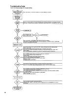
Страница 77: ...77 Honeywell Hot Surface to Pilot Trouble Shooting Guide ...
Страница 91: ...91 THIS PAGE LEFT BLANK INTENTIONALLY ...
Страница 92: ...92 ...
Страница 96: ...96 ...
Страница 99: ...99 THIS PAGE LEFT BLANK INTENTIONALLY ...
Страница 100: ...100 ...

