


23
VI. Gas Piping
G
N
I
N
R
A
W
o
t
y
l
p
p
u
s
s
a
g
e
p
i
p
y
l
r
e
p
o
r
p
o
t
e
r
u
li
a
F
d
n
a
n
o
i
t
a
r
e
p
o
r
e
p
o
r
p
m
i
n
i
t
l
u
s
e
r
y
a
m
r
e
li
o
b
s
y
a
w
l
A
.
e
r
u
t
c
u
r
t
s
r
o
r
e
li
o
b
e
h
t
o
t
e
g
a
m
a
d
e
e
r
f
k
a
e
l
y
l
e
t
u
l
o
s
b
a
s
i
g
n
i
p
i
p
s
a
g
e
r
u
s
s
a
e
h
t
r
o
f
e
p
y
t
d
n
a
e
z
i
s
r
e
p
o
r
p
e
h
t
f
o
d
n
a
.
d
a
o
l
d
e
t
c
e
n
n
o
c
y
a
m
r
o
t
a
l
u
g
e
r
e
r
u
s
s
e
r
p
s
a
g
l
a
n
o
i
t
i
d
d
a
n
A
.
r
e
il
p
p
u
s
s
a
g
t
l
u
s
n
o
C
.
d
e
d
e
e
n
e
b
A.
Size gas Piping.
Design system to provide
adequate gas supply to boiler. Consider these factors:
1. Allowable pressure drop from point of delivery to
boiler. Maximum allowable system pressure is ½
psig. Actual point of delivery pressure may be less;
contact gas supplier for additional information.
Minimum gas valve inlet pressure is indicated on
Rating Label, located on the vestibule panel.
2. Maximum gas demand. Table 2 lists boiler input
rate. Also consider existing and expected future gas
utilization equipment (i.e. water heater, cooking
equipment).
Table 2: Rated Input
jurisdiction specifies a gravity factor be applied. For
specific gravity greater than 0.70, apply gravity
factor from Table 5. If exact specific gravity is not
shown choose next higher value.
For materials or conditions other than those listed
above, refer to the
National Fuel Gas Code
, NFPA
54/ANSI Z223.1 and/or CAN/CGA B149
Installation Codes, or size system using standard
engineering methods acceptable to authority having
jurisdiction.
G
N
I
N
R
A
W
n
o
s
d
n
u
o
p
m
o
c
d
a
e
r
h
t
r
e
p
o
r
p
e
s
u
o
t
e
r
u
li
a
F
f
o
s
k
a
e
l
n
i
t
l
u
s
e
r
y
a
m
s
r
o
t
c
e
n
n
o
c
s
a
g
ll
a
.
s
a
g
e
l
b
a
m
m
a
l
f
G
N
I
N
R
A
W
e
b
t
s
u
m
m
e
t
s
y
s
d
n
a
r
e
li
o
b
o
t
y
l
p
p
u
s
s
a
G
r
o
g
n
il
l
a
t
s
n
i
o
t
r
o
i
r
p
f
f
o
t
u
h
s
y
l
e
t
u
l
o
s
b
a
.
g
n
i
p
i
p
s
a
g
r
e
li
o
b
g
n
i
c
i
v
r
e
s
B.
Connect boiler gas valve
to gas supply system.
1. Use methods and materials in accordance with local
plumbing codes and requirements of gas supplier. In
absence of such requirements, follow the
National
Fuel Gas Code
, NFPA 54/ANSI Z223.1 and/or
CAN/CGA B149 Installation Codes.
2. Use thread (joint) compounds (pipe dope) resistant
to action of liquefied petroleum gas.
3. Install sediment trap, ground-joint union and manual
shut-off valve upstream of boiler gas valve and
outside jacket. See Figure 29.
3. Length of piping and number of fittings. Refer to
Table 3 for maximum capacity of Schedule 40 pipe.
Table 4 lists equivalent length for standard fittings.
4. Specific gravity of gas. Gas piping systems for gas
with a specific gravity of 0.70 or less can be sized
directly from Table 3, unless authority having
Figure 29: Recommended Gas Piping
r
e
li
o
B
l
e
d
o
M
r
e
b
m
u
N
y
ti
c
a
p
a
C
d
e
t
a
R
]
r
u
o
h
r
e
p
t
e
e
f
c
i
b
u
c
[
s
a
G
n
o
it
c
e
n
n
o
C
e
z
i
S
l
a
r
u
t
a
N
e
n
a
p
o
r
P
/
P
L
3
N
I
2
6
¾
4
2
½
4
N
I
5
0
1
2
4
½
5
N
I
0
4
1
6
5
½
6
N
I
5
7
1
0
7
½
7
N
I
0
1
2
4
8
¾
8
N
I
5
4
2
8
9
¾
9
N
I
0
8
2
2
1
1
¾
0
1
N
I
5
1
3
6
2
1
*
¾
1
1
N
I
9
4
3
½
9
3
1
*
¾
2
1
N
I
5
8
3
4
5
1
1
1
1
N
I
d
n
a
0
1
N
I
n
o
"
1
s
i
e
z
i
s
n
o
it
c
e
n
n
o
c
s
a
G
*
)
t
o
li
P
g
n
i
d
n
a
t
S
(
n
o
it
i
n
g
I
s
u
o
u
n
it
n
o
C
Содержание Independence
Страница 4: ... Figure 1 Dimensional Drawing ...
Страница 19: ...19 Figure 25 Recommended Water Piping for Circulator Zoned Heating System ...
Страница 20: ...20 Figure 25A Recommended Water Piping for Zone Valve Zoned Heating System ...
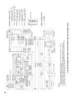
Страница 29: ...29 Figure 34 Vent Damper Schematic Wiring Diagram Figure 33 Vent Damper Harness to Limit ...
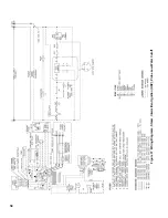
Страница 30: ...30 Figure 35 Wiring Diagrams Steam Continuous Ignition Standing Pilot Probe Low Water Cutoff ...
Страница 32: ...32 Figure 36 Wiring Diagrams Steam Intermittent Ignition EI Probe Low Water Cutoff ...
Страница 34: ...34 Figure 37 Wiring Diagrams Steam Intermittent Ignition HSP Probe Low Water Cutoff ...
Страница 36: ...36 Figure 38 Wiring Diagrams Steam Continuous Ignition Standing Pilot Float Low Water Cutoff ...
Страница 38: ...38 Figure 39 Wiring Diagrams Steam Intermittent Ignition EI Float Low Water Cutoff ...
Страница 40: ...40 Figure 40 Wiring Diagrams Steam Intermittent Ignition HSP Float Low Water Cutoff ...
Страница 42: ...42 Figure 41 Wiring Diagrams Water Continuous Ignition Standing Pilot Intermittent Circulation ...
Страница 44: ...44 Figure 42 Wiring Diagrams Water Intermittent Ignition EI Intermittent Circulation ...
Страница 46: ...46 Figure 43 Wiring Diagrams Water Intermittent Ignition HSP Intermittent Circulation ...
Страница 48: ...48 Figure 44 Wiring Diagrams Water Continuous Ignition Standing Pilot Gravity Circulation ...
Страница 50: ...50 Figure 45 Wiring Diagrams Water Intermittent Ignition EI Gravity Circulation ...
Страница 52: ...52 Figure 46 Wiring Diagrams Water Intermittent Ignition HSP Gravity Circulation ...
Страница 54: ...54 Figure 47 Wiring Diagrams Water Continuous Ignition Standing Pilot Tankless Heater ...
Страница 56: ...56 Figure 48 Wiring Diagrams Water Intermittent Ignition EI Tankless Heater ...
Страница 58: ...58 Figure 49 Wiring Diagrams Water Intermittent Ignition HSP Tankless Heater ...
Страница 61: ...61 Figure 53 Lighting Instructions Continuous Ignition System VR8200 and VR8300 Gas Valves ...
Страница 62: ...62 Figure 54 Lighting Instructions Continuous Ignition System 7000 ERHC Gas Valve ...
Страница 64: ...64 Figure 56 Operating Instructions Intermittent Ignition System EI VR8304 IN12 only Gas Valves ...
Страница 65: ...65 Figure 57 Operating Instructions Intermittent Ignition System HSP SV9501 and SV9601 ...
Страница 76: ...76 ...
Страница 77: ...77 Honeywell Hot Surface to Pilot Trouble Shooting Guide ...
Страница 91: ...91 THIS PAGE LEFT BLANK INTENTIONALLY ...
Страница 92: ...92 ...
Страница 96: ...96 ...
Страница 99: ...99 THIS PAGE LEFT BLANK INTENTIONALLY ...
Страница 100: ...100 ...


