


9
F.
Check pilot burner flame and main burner flames
through observation port.
1. Check pilot flame.
a. Continuous Ignition (Standing Pilot), Models
IN3 through IN7. See Figure 59. Pilot burner
produces a single flame. Flame should be steady,
medium hard blue enveloping 3/8 to ½ inch of
thermocouple.
b. Continuous Ignition (Standing Pilot), Models
IN8 through IN12. See Figure 60. Pilot burner
produces three (3) flames. Center flame should
be steady, medium hard blue enveloping 3/8 to ½
inch of thermocouple.
c. Electronic Ignition (EI), Models IN3 through
IN12. See Figure 61. Pilot should be lit only
after completing Step 3. Pilot burner produces
three (3) flames. Center flame should be steady,
medium hard blue enveloping 3/8 to ½ inch of
sensing probe.
N
O
I
T
U
A
C
t
n
e
m
n
o
r
i
v
n
e
n
a
n
i
r
e
li
o
b
s
i
h
t
g
n
i
t
a
r
e
p
o
d
i
o
v
A
y
r
d
,
s
r
e
b
i
f
n
o
i
t
a
l
u
s
n
i
e
s
o
o
l
,
t
s
u
d
w
a
s
e
r
e
h
w
s
i
r
e
li
o
b
f
I
.
t
n
e
s
e
r
p
e
r
a
.
c
t
e
,
t
s
u
d
ll
a
w
r
e
n
r
u
b
e
h
t
,
s
n
o
i
t
i
d
n
o
c
e
s
e
h
t
r
e
d
n
u
d
e
t
a
r
e
p
o
d
n
a
d
e
n
a
e
l
c
e
b
t
s
u
m
s
t
r
o
p
d
n
a
r
o
i
r
e
t
n
i
.
n
o
i
t
a
r
e
p
o
r
e
p
o
r
p
e
r
u
s
n
i
o
t
y
li
a
d
d
e
t
c
e
p
s
n
i
d. Hot Surface to Pilot Ignition (HSP), Models IN3
through IN9. See Figure 62. Pilot should be lit
only after completing Step 3. Pilot burner
produces three (3) flames. Center flame should
be steady, medium hard blue enveloping 3/8 to ½
inch of sensing probe.
2. Adjust thermostat to highest setting.
3. Check main burner flames. See Figure 63 or 64.
Flame should have clearly defined inner cones with
no yellow tipping. Orange-yellow streaks caused by
dust should not be confused with true yellow
tipping.
4. Adjust thermostat to normal setting.
G.
Check thermostat operation.
Raise and lower
temperature setting to start and stop boiler operation.
H.
Check ignition system shutoff.
Gas valve should close
and pilot and main burners extinguish.
1. Continuous Ignition (Standing Pilot): disconnect
thermocouple from gas valve.
2. Electronic Ignition (EI): disconnect igniter/sensor
cable from ignition module terminal "9".
3. Hot Surface to Pilot Ignition (HSP): disconnect
igniter/sensor (3 wire quick connect) from gas valve.
I.
Check low water cutoff (steam only).
1. Adjust thermostat to highest setting.
2. With boiler operating, open drain and slowly drain
boiler.
N
O
I
T
U
A
C
.
s
s
a
l
g
e
g
u
a
g
w
o
l
e
b
n
i
a
r
d
t
o
n
o
D
3. Main burners will extinguish when water level drops
below low water cutoff. Water should still be visible
in gauge glass. Verify limit, thermostat or other
controls have not shut off boiler.
4. Adjust thermostat to lowest setting. Refill boiler to
normal water line.
J.
Check Limit.
1. Adjust thermostat to highest setting.
2. Steam: Observe pressure gauge. When pressure is
indicated, adjust limit to setting below observed
pressure. Main burners should extinguish.
G
N
I
N
R
A
W
ll
i
w
e
t
a
r
t
u
p
n
i
s
a
g
t
s
u
j
d
a
y
l
r
e
p
o
r
p
o
t
e
r
u
li
a
F
e
h
t
f
o
g
n
i
r
i
f
r
e
d
n
u
r
o
g
n
i
r
i
f
r
e
v
o
n
i
t
l
u
s
e
r
r
e
li
o
b
e
f
a
s
n
u
d
n
a
r
e
p
o
r
p
m
I
.
e
c
n
a
il
p
p
a
.
t
l
u
s
e
r
y
a
m
n
o
i
t
a
r
e
p
o
3. Water: Observe temperature gauge. When
temperature exceeds limit set point main burners
should extinguish.
4. Adjust limit to setting above observed reading. Main
burners should reignite.
5. Adjust thermostat to lowest setting. Adjust limit to
desired setting.
K.
Adjust gas input rate to boiler.
Natural Gas.
1. Adjust thermostat to highest setting.
2. Check manifold gas pressure. Manifold pressure is
listed on Rating Label.
a. Models IN3-IN12 with Standing Pilot, IN3-IN9
with Hot Surface to Pilot and IN3-IN11 with
Electronic Ignition. Adjust gas valve pressure
regulator as necessary (turn adjustment screw
counterclockwise to decrease manifold pressure,
or clockwise to increase manifold pressure). If
pressure can not be attained, check gas valve
inlet pressure. If less than minimum gas supply
pressure listed on Rating Label, contact gas
supplier for assistance.
b. Model IN12 with Electronic or HSP Ignition
Only.
i
. Turn off gas valve not having pilot control.
ii
. On gas valve with pilot control, adjust gas
valve pressure regulator to obtain required
manifold pressure, or if unattainable, highest
pressure without forcing adjustment screw
Содержание Independence
Страница 4: ... Figure 1 Dimensional Drawing ...
Страница 19: ...19 Figure 25 Recommended Water Piping for Circulator Zoned Heating System ...
Страница 20: ...20 Figure 25A Recommended Water Piping for Zone Valve Zoned Heating System ...
Страница 29: ...29 Figure 34 Vent Damper Schematic Wiring Diagram Figure 33 Vent Damper Harness to Limit ...
Страница 30: ...30 Figure 35 Wiring Diagrams Steam Continuous Ignition Standing Pilot Probe Low Water Cutoff ...
Страница 32: ...32 Figure 36 Wiring Diagrams Steam Intermittent Ignition EI Probe Low Water Cutoff ...
Страница 34: ...34 Figure 37 Wiring Diagrams Steam Intermittent Ignition HSP Probe Low Water Cutoff ...
Страница 36: ...36 Figure 38 Wiring Diagrams Steam Continuous Ignition Standing Pilot Float Low Water Cutoff ...
Страница 38: ...38 Figure 39 Wiring Diagrams Steam Intermittent Ignition EI Float Low Water Cutoff ...
Страница 40: ...40 Figure 40 Wiring Diagrams Steam Intermittent Ignition HSP Float Low Water Cutoff ...
Страница 42: ...42 Figure 41 Wiring Diagrams Water Continuous Ignition Standing Pilot Intermittent Circulation ...
Страница 44: ...44 Figure 42 Wiring Diagrams Water Intermittent Ignition EI Intermittent Circulation ...
Страница 46: ...46 Figure 43 Wiring Diagrams Water Intermittent Ignition HSP Intermittent Circulation ...
Страница 48: ...48 Figure 44 Wiring Diagrams Water Continuous Ignition Standing Pilot Gravity Circulation ...
Страница 50: ...50 Figure 45 Wiring Diagrams Water Intermittent Ignition EI Gravity Circulation ...
Страница 52: ...52 Figure 46 Wiring Diagrams Water Intermittent Ignition HSP Gravity Circulation ...
Страница 54: ...54 Figure 47 Wiring Diagrams Water Continuous Ignition Standing Pilot Tankless Heater ...
Страница 56: ...56 Figure 48 Wiring Diagrams Water Intermittent Ignition EI Tankless Heater ...
Страница 58: ...58 Figure 49 Wiring Diagrams Water Intermittent Ignition HSP Tankless Heater ...
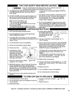
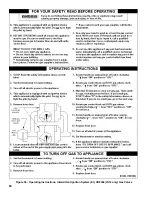
Страница 61: ...61 Figure 53 Lighting Instructions Continuous Ignition System VR8200 and VR8300 Gas Valves ...
Страница 62: ...62 Figure 54 Lighting Instructions Continuous Ignition System 7000 ERHC Gas Valve ...
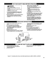
Страница 64: ...64 Figure 56 Operating Instructions Intermittent Ignition System EI VR8304 IN12 only Gas Valves ...
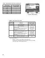
Страница 65: ...65 Figure 57 Operating Instructions Intermittent Ignition System HSP SV9501 and SV9601 ...
Страница 76: ...76 ...
Страница 77: ...77 Honeywell Hot Surface to Pilot Trouble Shooting Guide ...
Страница 91: ...91 THIS PAGE LEFT BLANK INTENTIONALLY ...
Страница 92: ...92 ...
Страница 96: ...96 ...
Страница 99: ...99 THIS PAGE LEFT BLANK INTENTIONALLY ...
Страница 100: ...100 ...


