73
X. Service Instructions
A.
General.
Inspection and service should be conducted
annually, except as noted. Turn off electrical power and
gas supply while conducting service or maintenance.
Follow instructions TO TURN OFF GAS TO
APPLIANCE. See Figures 53, 54, 55, 56 or 57.
B.
Maintenance of Low Water Cutoff
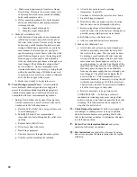
1. McDonnell & Miller PS-802 or Hydrolevel
CycleGard CG400 Probe Style Only.
a. Drain boiler to point below Tapping 'K'. See
Figure 2.
b. Disconnect wire(s) connecting control and probe.
c. Remove control from probe.
R
E
G
N
A
D
e
r
u
s
s
e
r
p
o
r
e
z
t
a
s
i
r
e
li
o
b
e
h
t
t
a
h
t
e
r
u
s
s
A
t
o
n
o
D
.
e
b
o
r
p
O
C
W
L
e
h
t
g
n
i
v
o
m
e
r
e
r
o
f
e
b
t
a
h
t
e
t
a
c
i
d
n
i
o
t
e
g
u
a
g
e
r
u
s
s
e
r
p
e
h
t
n
o
y
l
e
r
e
h
t
n
e
p
O
.
e
r
u
s
s
e
r
p
o
r
e
z
t
a
s
i
r
e
li
o
b
e
h
t
e
r
u
s
s
e
r
p
l
a
n
r
e
t
n
i
ll
a
e
v
e
il
e
r
o
t
e
v
l
a
v
y
t
e
f
a
s
e
g
r
a
h
c
s
i
d
e
v
l
a
v
y
t
e
f
a
S
.
g
n
i
d
e
e
c
o
r
p
o
t
r
o
i
r
p
l
a
i
t
n
e
t
o
p
e
h
t
t
a
h
t
h
c
u
s
d
e
p
i
p
e
b
t
s
u
m
g
n
i
p
i
p
.
d
e
t
a
n
i
m
il
e
s
i
s
n
r
u
b
r
o
f
d. Unscrew probe from Tapping 'K'. Inspect for
scale and sediment buildup.
e. Remove light deposits with damp cloth soaked
with vinegar.
f. Remove stubborn deposits using diluted
phosphoric acid (H
2
PO
4
) solution, 3 parts water
to 1 part phosphoric acid. Normal operation will
occur with up to 0.2 inch of contamination. If
scale or contamination exceeds 0.2 inches, clean
probe more frequently.
g. Clean Tapping 'K' to remove old pipe dope and
other foreign matter.
h. Apply moderate amount of good quality pipe
dope to probe threads, leaving two end threads
bare. Install probe in Tapping 'K'. Mount control
on probe. Attach wire(s) between control and
probe.
i. Fill boiler to normal waterline. Add water
treatment as needed.
2. McDonnell & Miller 67 Float Style Only.
a. Weekly (or more frequently if necessary). Open
blow-off valve to flush sediment chamber.
Follow instructions on Blow-Down Card affixed
to Jacket adjacent to low water cutoff.
b. Annually. Dismantle to extent necessary to
remove obstructions and insure proper function
of working parts.
R
E
G
N
A
D
r
e
t
a
w
t
o
h
y
r
e
v
d
n
a
,
s
t
r
a
p
g
n
i
v
o
m
,
y
t
i
c
i
r
t
c
e
l
e
e
g
a
t
l
o
v
h
g
i
h
,
s
a
g
e
l
b
a
m
m
a
l
f
s
e
s
u
r
e
li
o
b
s
i
h
T
e
h
t
t
a
h
t
d
n
a
f
f
o
e
r
a
s
e
il
p
p
u
s
r
e
w
o
p
c
i
r
t
c
e
l
e
d
n
a
s
a
g
ll
a
t
a
h
t
e
r
u
s
s
A
.
e
r
u
s
s
e
r
p
h
g
i
h
r
e
d
n
u
.
e
c
i
v
r
e
s
r
o
y
l
b
m
e
s
s
a
s
i
d
y
n
a
g
n
i
t
p
m
e
t
t
a
e
r
o
f
e
b
l
o
o
c
s
i
e
r
u
t
a
r
e
p
m
e
t
r
e
t
a
w
y
n
a
g
n
i
t
p
m
e
t
t
a
e
r
o
f
e
b
f
f
o
e
r
a
s
e
h
c
t
i
w
s
t
c
e
n
n
o
c
s
i
d
l
a
c
i
r
t
c
e
l
e
d
n
a
s
e
v
l
a
v
s
a
g
ll
a
t
a
h
t
e
r
u
s
s
A
.
e
c
i
v
r
e
s
r
o
y
l
b
m
e
s
s
a
s
i
d
.
r
e
li
o
b
e
h
t
f
o
y
t
i
n
i
c
i
v
e
h
t
n
i
r
i
a
e
h
t
n
i
t
n
e
s
e
r
p
s
i
s
a
g
f
i
k
r
o
w
e
c
i
v
r
e
s
y
n
a
t
p
m
e
t
t
a
t
o
n
o
D
.
e
c
i
v
e
d
l
o
r
t
n
o
c
y
n
a
h
t
i
w
r
e
p
m
a
t
r
o
e
v
o
m
e
r
,
y
f
i
d
o
m
r
e
v
e
N
G
N
I
N
R
A
W
e
c
i
v
r
e
s
d
e
c
n
e
i
r
e
p
x
e
d
n
a
d
e
ll
i
k
s
y
b
d
e
r
i
a
p
e
r
d
n
a
d
e
c
i
v
r
e
s
e
b
y
l
n
o
t
s
u
m
r
e
li
o
b
s
i
h
T
.
s
n
a
i
c
i
n
h
c
e
t
.
s
l
e
d
o
m
l
a
c
i
t
n
e
d
i
h
t
i
w
e
b
t
s
u
m
y
e
h
t
,
d
e
c
a
l
p
e
r
e
r
a
s
l
o
r
t
n
o
c
y
n
a
f
I
s
n
o
i
t
c
e
s
e
h
t
ll
a
n
i
d
e
n
i
a
t
n
o
c
s
g
n
i
n
r
a
w
d
n
a
s
n
o
i
t
c
u
r
t
s
n
i
e
h
t
ll
a
w
o
ll
o
f
d
n
a
d
n
a
t
s
r
e
d
n
u
,
d
a
e
R
.l
a
u
n
a
m
s
i
h
t
f
o
e
r
u
s
s
a
d
n
a
s
e
r
i
w
e
h
t
l
e
b
a
l
y
l
r
a
e
l
c
,
e
c
i
v
r
e
s
g
n
i
r
u
d
d
e
t
c
e
n
n
o
c
s
i
d
e
r
a
s
e
r
i
w
l
a
c
i
r
t
c
e
l
e
y
n
a
f
I
.
y
l
r
e
p
o
r
p
d
e
t
c
e
n
n
o
c
e
r
e
r
a
s
e
r
i
w
e
h
t
t
a
h
t
.
r
e
li
o
b
s
i
h
t
f
o
t
n
e
n
o
p
m
o
c
r
o
l
o
r
t
n
o
c
g
n
i
t
a
r
e
p
o
r
o
y
t
e
f
a
s
y
n
a
s
s
a
p
y
b
r
o
t
u
o
p
m
u
j
r
e
v
e
N
e
h
t
f
o
L
L
A
n
i
d
e
n
i
a
t
n
o
c
s
g
n
i
n
r
a
w
d
n
a
s
n
o
i
t
c
u
r
t
s
n
i
e
h
t
ll
a
w
o
ll
o
f
d
n
a
d
n
a
t
s
r
e
d
n
u
,
d
a
e
R
.
s
l
a
u
n
a
m
n
o
i
t
c
u
r
t
s
n
i
t
n
e
n
o
p
m
o
c
e
r
o
f
e
b
y
l
r
e
p
o
r
p
g
n
i
t
a
r
e
p
o
e
r
a
s
t
n
e
n
o
p
m
o
c
d
n
a
s
l
o
r
t
n
o
c
g
n
i
t
a
r
e
p
o
d
n
a
y
t
e
f
a
s
ll
a
t
a
h
t
e
r
u
s
s
A
.
e
c
i
v
r
e
s
n
i
k
c
a
b
r
e
li
o
b
e
h
t
g
n
i
c
a
l
p
Содержание Independence
Страница 4: ... Figure 1 Dimensional Drawing ...
Страница 19: ...19 Figure 25 Recommended Water Piping for Circulator Zoned Heating System ...
Страница 20: ...20 Figure 25A Recommended Water Piping for Zone Valve Zoned Heating System ...
Страница 29: ...29 Figure 34 Vent Damper Schematic Wiring Diagram Figure 33 Vent Damper Harness to Limit ...
Страница 30: ...30 Figure 35 Wiring Diagrams Steam Continuous Ignition Standing Pilot Probe Low Water Cutoff ...
Страница 32: ...32 Figure 36 Wiring Diagrams Steam Intermittent Ignition EI Probe Low Water Cutoff ...
Страница 34: ...34 Figure 37 Wiring Diagrams Steam Intermittent Ignition HSP Probe Low Water Cutoff ...
Страница 36: ...36 Figure 38 Wiring Diagrams Steam Continuous Ignition Standing Pilot Float Low Water Cutoff ...
Страница 38: ...38 Figure 39 Wiring Diagrams Steam Intermittent Ignition EI Float Low Water Cutoff ...
Страница 40: ...40 Figure 40 Wiring Diagrams Steam Intermittent Ignition HSP Float Low Water Cutoff ...
Страница 42: ...42 Figure 41 Wiring Diagrams Water Continuous Ignition Standing Pilot Intermittent Circulation ...
Страница 44: ...44 Figure 42 Wiring Diagrams Water Intermittent Ignition EI Intermittent Circulation ...
Страница 46: ...46 Figure 43 Wiring Diagrams Water Intermittent Ignition HSP Intermittent Circulation ...
Страница 48: ...48 Figure 44 Wiring Diagrams Water Continuous Ignition Standing Pilot Gravity Circulation ...
Страница 50: ...50 Figure 45 Wiring Diagrams Water Intermittent Ignition EI Gravity Circulation ...
Страница 52: ...52 Figure 46 Wiring Diagrams Water Intermittent Ignition HSP Gravity Circulation ...
Страница 54: ...54 Figure 47 Wiring Diagrams Water Continuous Ignition Standing Pilot Tankless Heater ...
Страница 56: ...56 Figure 48 Wiring Diagrams Water Intermittent Ignition EI Tankless Heater ...
Страница 58: ...58 Figure 49 Wiring Diagrams Water Intermittent Ignition HSP Tankless Heater ...
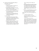
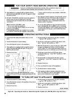
Страница 61: ...61 Figure 53 Lighting Instructions Continuous Ignition System VR8200 and VR8300 Gas Valves ...
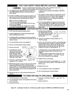
Страница 62: ...62 Figure 54 Lighting Instructions Continuous Ignition System 7000 ERHC Gas Valve ...
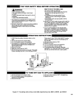
Страница 64: ...64 Figure 56 Operating Instructions Intermittent Ignition System EI VR8304 IN12 only Gas Valves ...
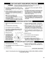
Страница 65: ...65 Figure 57 Operating Instructions Intermittent Ignition System HSP SV9501 and SV9601 ...
Страница 76: ...76 ...
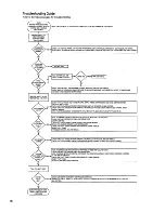
Страница 77: ...77 Honeywell Hot Surface to Pilot Trouble Shooting Guide ...
Страница 91: ...91 THIS PAGE LEFT BLANK INTENTIONALLY ...
Страница 92: ...92 ...
Страница 96: ...96 ...
Страница 99: ...99 THIS PAGE LEFT BLANK INTENTIONALLY ...
Страница 100: ...100 ...

