24
Table 4: Fitting Equivalent Lengths
Table 5: Specific Gravity Correction Factors
4. All above ground gas piping upstream from manual
gas valve must be electrically continuous and
bonded to a grounding electrode. Do not use gas
piping as a grounding electrode. Refer to the
National Electrical Code
, ANSI/NFPA 70 and/or
CSA C22.1 Electrical Code.
C.
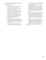
Pressure Test.
The boiler and its gas connection must
be leak tested before placing boiler in operation.
1. Protect boiler gas valve. For all testing over ½ psig,
boiler an its individual shut-off valve must be
disconnected from gas supply piping. For testing at
½ psig or less, isolate boiler from gas supply piping
by closing boiler's individual manual shut-off valve.
2. Using soap solution, or similar non-combustible
solution, electronic leak detector or other approved
method. Check that boiler gas piping valves, and all
other components are leak free. Eliminate any
leaks.
R
E
G
N
A
D
s
e
m
a
l
f
n
e
p
o
,
s
e
l
d
n
a
c
,
s
e
h
c
t
a
m
e
s
u
t
o
n
o
D
.
s
k
a
e
l
r
o
f
k
c
e
h
c
o
t
e
c
r
u
o
s
n
o
i
t
i
n
g
i
r
e
h
t
o
r
o
Table 3: Maximum Capacity of Schedule 40 Pipe in CFH for Gas Pressures of 0. psig or Less
E
C
I
T
O
N
n
e
e
b
e
v
a
h
l
e
v
e
l
a
e
s
e
v
o
b
a
t
e
e
f
0
0
0
,
2
n
a
h
t
r
e
t
a
e
r
g
s
e
d
u
t
i
t
l
a
t
a
n
o
i
t
a
ll
a
t
s
n
i
r
o
f
t
li
u
b
s
r
e
li
o
b
A
S
U
e
h
t
r
e
p
l
e
v
e
l
a
e
s
e
v
o
b
a
t
e
e
f
0
0
0
,
1
r
e
p
t
n
e
c
r
e
p
4
e
t
a
r
t
u
p
n
i
s
a
g
e
c
u
d
e
r
o
t
d
e
c
i
f
i
r
o
y
ll
a
i
c
e
p
s
'
s
r
e
li
o
b
n
a
i
d
a
n
a
C
.
F
x
i
d
n
e
p
p
A
d
n
a
2
.
1
.
8
n
o
i
t
c
e
S
,
1
.
3
2
2
Z
I
S
N
A
/
4
5
A
P
F
N
,
e
d
o
C
s
a
G
l
e
u
F
l
a
n
o
i
t
a
N
e
h
t
y
b
e
l
b
a
i
f
i
t
n
e
d
i
e
r
a
s
l
e
d
o
m
r
e
li
o
b
e
d
u
t
i
t
l
a
h
g
i
H
.l
e
b
a
l
g
n
i
t
a
r
e
h
t
n
o
d
e
t
a
c
i
d
n
i
s
i
g
n
i
z
i
s
e
c
i
f
i
r
o
:
l
e
b
a
l
g
n
i
t
a
r
e
h
t
n
o
x
i
f
f
u
s
r
e
b
m
u
n
l
e
d
o
m
e
h
t
n
i
t
i
g
i
d
d
r
i
h
t
n
o
i
t
a
v
e
l
e
.
t
f
0
0
0
2
n
a
h
t
s
s
e
l
2
_
_
-
_
_
_
N
I
_
)
a
d
a
n
a
C
(
n
o
i
t
a
v
e
l
e
.
t
f
0
0
5
4
o
t
0
0
0
2
4
_
_
-
_
_
_
N
I
_
)
A
S
U
(
n
o
i
t
a
v
e
l
e
.
t
f
0
0
0
5
o
t
0
0
0
2
5
_
_
-
_
_
_
N
I
_
h
t
g
n
e
L
]
t
e
e
F
[
p
o
r
D
e
r
u
s
s
e
r
P
.
c
.
w
h
c
n
i
3
.
0
p
o
r
D
e
r
u
s
s
e
r
P
.
c
.
w
h
c
n
i
5
.
0
½
¾
1
¼
1
½
¾
1
¼
1
0
1
2
3
1
8
7
2
0
2
5
0
5
0
,
1
5
7
1
0
6
3
0
8
6
0
0
4
,
1
0
2
2
9
0
9
1
0
5
3
0
3
7
0
2
1
0
5
2
5
6
4
0
5
9
0
3
3
7
2
5
1
5
8
2
0
9
5
7
9
0
0
2
5
7
3
0
7
7
0
4
3
6
0
3
1
5
4
2
0
0
5
2
8
0
7
1
0
2
3
0
6
6
0
5
6
5
5
1
1
5
1
2
0
4
4
3
7
1
5
1
5
8
2
0
8
5
0
6
0
5
5
0
1
5
9
1
0
0
4
6
6
8
3
1
0
6
2
0
3
5
0
7
6
4
6
9
0
8
1
0
7
3
1
6
5
2
1
0
4
2
0
9
4
0
8
3
4
0
9
0
7
1
0
5
3
7
5
8
1
1
0
2
2
0
6
4
0
9
0
4
4
8
0
6
1
0
2
3
3
5
0
1
1
5
0
2
0
3
4
0
0
1
8
3
9
7
0
5
1
5
0
3
0
5
3
0
1
5
9
1
0
0
4
g
n
i
t
t
i
F
e
z
i
S
e
p
i
P
l
a
n
i
m
o
N
½
¾
1
¼
1
ll
E
°
5
4
7
.
0
1
2
.
1
6
.
1
ll
E
°
0
9
6
.
1
1
.
2
6
.
2
5
.
3
s
A
(
e
e
T
)
w
o
b
l
E
1
.
3
1
.
4
2
.
5
9
.
6
c
if
i
c
e
p
S
y
t
i
v
a
r
G
n
o
it
c
e
r
r
o
C
r
o
t
c
a
F
c
if
i
c
e
p
S
y
t
i
v
a
r
G
n
o
it
c
e
r
r
o
C
r
o
t
c
a
F
0
5
.
0
0
1
.
1
0
3
.
1
7
0
.
1
5
5
.
0
4
0
.
1
0
4
.
1
4
0
.
1
0
6
.
0
0
0
.
1
0
5
.
1
0
0
.
1
5
6
.
0
6
9
.
0
0
6
.
1
7
9
.
0
0
7
.
0
3
9
.
0
0
7
.
1
4
9
.
0
5
7
.
0
0
9
.
0
0
8
.
0
7
8
.
0
Содержание Independence
Страница 4: ... Figure 1 Dimensional Drawing ...
Страница 19: ...19 Figure 25 Recommended Water Piping for Circulator Zoned Heating System ...
Страница 20: ...20 Figure 25A Recommended Water Piping for Zone Valve Zoned Heating System ...
Страница 29: ...29 Figure 34 Vent Damper Schematic Wiring Diagram Figure 33 Vent Damper Harness to Limit ...
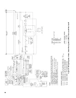
Страница 30: ...30 Figure 35 Wiring Diagrams Steam Continuous Ignition Standing Pilot Probe Low Water Cutoff ...
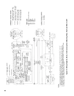
Страница 32: ...32 Figure 36 Wiring Diagrams Steam Intermittent Ignition EI Probe Low Water Cutoff ...
Страница 34: ...34 Figure 37 Wiring Diagrams Steam Intermittent Ignition HSP Probe Low Water Cutoff ...
Страница 36: ...36 Figure 38 Wiring Diagrams Steam Continuous Ignition Standing Pilot Float Low Water Cutoff ...
Страница 38: ...38 Figure 39 Wiring Diagrams Steam Intermittent Ignition EI Float Low Water Cutoff ...
Страница 40: ...40 Figure 40 Wiring Diagrams Steam Intermittent Ignition HSP Float Low Water Cutoff ...
Страница 42: ...42 Figure 41 Wiring Diagrams Water Continuous Ignition Standing Pilot Intermittent Circulation ...
Страница 44: ...44 Figure 42 Wiring Diagrams Water Intermittent Ignition EI Intermittent Circulation ...
Страница 46: ...46 Figure 43 Wiring Diagrams Water Intermittent Ignition HSP Intermittent Circulation ...
Страница 48: ...48 Figure 44 Wiring Diagrams Water Continuous Ignition Standing Pilot Gravity Circulation ...
Страница 50: ...50 Figure 45 Wiring Diagrams Water Intermittent Ignition EI Gravity Circulation ...
Страница 52: ...52 Figure 46 Wiring Diagrams Water Intermittent Ignition HSP Gravity Circulation ...
Страница 54: ...54 Figure 47 Wiring Diagrams Water Continuous Ignition Standing Pilot Tankless Heater ...
Страница 56: ...56 Figure 48 Wiring Diagrams Water Intermittent Ignition EI Tankless Heater ...
Страница 58: ...58 Figure 49 Wiring Diagrams Water Intermittent Ignition HSP Tankless Heater ...
Страница 61: ...61 Figure 53 Lighting Instructions Continuous Ignition System VR8200 and VR8300 Gas Valves ...
Страница 62: ...62 Figure 54 Lighting Instructions Continuous Ignition System 7000 ERHC Gas Valve ...
Страница 64: ...64 Figure 56 Operating Instructions Intermittent Ignition System EI VR8304 IN12 only Gas Valves ...
Страница 65: ...65 Figure 57 Operating Instructions Intermittent Ignition System HSP SV9501 and SV9601 ...
Страница 76: ...76 ...
Страница 77: ...77 Honeywell Hot Surface to Pilot Trouble Shooting Guide ...
Страница 91: ...91 THIS PAGE LEFT BLANK INTENTIONALLY ...
Страница 92: ...92 ...
Страница 96: ...96 ...
Страница 99: ...99 THIS PAGE LEFT BLANK INTENTIONALLY ...
Страница 100: ...100 ...


