


28
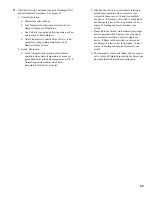
Table : Thermostat Heat Anticipator Settings
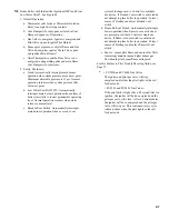
Set heat anticipator to match system requirements. See
Table 6. In general, setting heat anticipator too low will
cause boiler to short cycle without bringing heated
space up to temperature. Setting heat anticipator too
high will allow boiler to operate longer than necessary
and overheat space.
D.
Wire thermostat.
Provide Class II circuit between
thermostat and boiler.
1. Steam or Water with gravity circulation or tankless
heater. Remove transformer from junction box.
Connect one wire from thermostat to blue wire(s).
Connect additional wire from thermostat to brown
wire or red wire for water with tankless heater.
2. Water with intermittent circulation and without
tankless heater. Connect one wire from thermostat
to Terminal "T" and additional wire to terminal
"TV".
E.
Alliance Indirect Water Heater
(if used).
1. For wiring refer to wiring diagrams located in this
section and Alliance Installation Operating and
Service Instructions.
2. Attach junction box extension (4 - 11/16 square) to
junction box on boiler.
3. Steam Boilers only. Verify temperature limit
(Honeywell L4006 or equal, which is installer
supplied) is installed in Tapping "P", refer to
Section V: Piping and Trim.
F.
Wire control circuit
as shown in the appropriate
wiring diagram. See Table 6.
1. A separate electrical circuit must be run from the
main electrical service with an over-current device/
disconnect in the circuit. A service switch is
recommended and may be required by some local
jurisdictions. Boiler is rated for 120 VAC, 60 hertz,
less than 12 amperes.
2. For zone valve wiring, provide separate 24V
transformer rather than attempting to use boiler
mounted control. Consult zone valve manufacturer
for assistance.
G.
Wiring diagram and sequence of operation.
Locate
the system type you are interested in from Table 6, then
refer to the page indicated.
1. Vent Damper Sequence of Operation. See Figure
34.
a. Vent Damper is continuously powered at
Terminal 1.
b. When there is a call for heat, the damper relay
coil is energized through Terminal 5 if all limits
ahead of the damper are satisfied.
c. Relay coil closes contacts, energizing damper
motor, causing damper to open.
d. When the damper blade reaches the fully open
position, power is sent back to the boiler limit/
ignition circuit through Terminal 2 and the
damper motor is de-energized.
e. When the call for heat is satisfied, the damper
relay coil is de-energized—closing contacts
which energize the damper motor. This causes
the damper to close. When the damper blade
reaches the fully closed position, the damper
motor is de-energized.
e
p
y
T
m
e
t
s
y
S
m
e
t
s
y
S
n
o
it
i
n
g
I
t
a
e
H
r
o
t
a
p
i
c
it
n
A
)
1
(
g
n
it
t
e
S
s
u
o
u
n
it
n
o
C
)
t
o
li
P
g
n
i
d
n
a
t
S
(
)I
E
(
t
n
e
tt
i
m
r
e
t
n
I
)
P
S
H
(
t
n
e
tt
i
m
r
e
t
n
I
e
b
o
r
P
h
ti
w
m
a
e
t
S
r
o
2
0
8
-
S
P
r
e
ll
i
M
&
ll
e
n
n
o
D
c
M
(
)
0
0
4
-
B
G
C
l
e
v
e
l
o
r
d
y
H
ff
o
t
u
C
r
e
t
a
W
w
o
L
e
g
a
P
,
5
3
e
r
u
g
i
F
0
3
3
e
g
a
P
,
6
3
e
r
u
g
i
F
2
3
e
g
a
P
,
7
3
e
r
u
g
i
F
4
8
.
0
t
a
o
l
F
h
t
i
w
m
a
e
t
S
)
7
6
r
e
ll
i
M
&
ll
e
n
n
o
D
c
M
(
ff
o
t
u
C
r
e
t
a
W
w
o
L
3
e
g
a
P
,
8
3
e
r
u
g
i
F
6
3
e
g
a
P
,
9
3
e
r
u
g
i
F
8
e
g
a
P
,
0
4
e
r
u
g
i
F
0
4
8
.
0
)
n
o
it
a
l
u
c
r
i
C
t
n
e
t
t
i
m
r
e
t
n
I
(
r
e
t
a
W
4
e
g
a
P
,
1
4
e
r
u
g
i
F
2
4
e
g
a
P
,
2
4
e
r
u
g
i
F
4
4
e
g
a
P
,
3
4
e
r
u
g
i
F
6
3
.
0
)
n
o
it
a
l
u
c
r
i
C
y
t
i
v
a
r
G
(
r
e
t
a
W
4
e
g
a
P
,
4
4
e
r
u
g
i
F
8
e
g
a
P
,
5
4
e
r
u
g
i
F
0
5
5
e
g
a
P
,
6
4
e
r
u
g
i
F
2
3
.
0
r
e
t
a
e
H
s
s
e
l
k
n
a
T
h
t
i
w
r
e
t
a
W
5
e
g
a
P
,
7
4
e
r
u
g
i
F
4
5
e
g
a
P
,
8
4
e
r
u
g
i
F
6
5
e
g
a
p
,
9
4
e
r
u
g
i
F
8
6
.
0
1
.
0
y
b
g
n
it
t
e
s
r
o
t
a
p
i
c
it
n
a
t
a
e
h
e
c
u
d
e
r
,
g
n
it
t
e
s
e
r
u
t
a
r
e
p
m
e
t
s
't
a
t
s
o
m
r
e
h
t
e
v
o
b
a
t
a
e
h
r
e
v
o
o
t
s
d
n
e
t
m
e
t
s
y
s
fI
)
1
(
t
a
e
h
e
s
a
e
r
c
n
i
,
e
r
u
t
a
r
e
p
m
e
t
m
o
o
r
d
e
r
i
s
e
d
g
n
i
h
c
a
e
r
t
u
o
h
t
i
w
e
l
c
y
c
t
r
o
h
s
o
t
s
d
n
e
t
m
e
t
s
y
s
fI
.
s
p
m
a
2
.
0
r
o
.
s
p
m
a
2
.
0
r
o
1
.
0
y
b
g
n
it
t
e
s
r
o
t
a
p
i
c
it
n
a
Содержание Independence
Страница 4: ... Figure 1 Dimensional Drawing ...
Страница 19: ...19 Figure 25 Recommended Water Piping for Circulator Zoned Heating System ...
Страница 20: ...20 Figure 25A Recommended Water Piping for Zone Valve Zoned Heating System ...
Страница 29: ...29 Figure 34 Vent Damper Schematic Wiring Diagram Figure 33 Vent Damper Harness to Limit ...
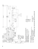
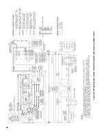
Страница 30: ...30 Figure 35 Wiring Diagrams Steam Continuous Ignition Standing Pilot Probe Low Water Cutoff ...
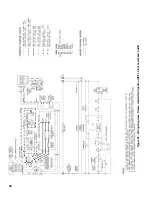
Страница 32: ...32 Figure 36 Wiring Diagrams Steam Intermittent Ignition EI Probe Low Water Cutoff ...
Страница 34: ...34 Figure 37 Wiring Diagrams Steam Intermittent Ignition HSP Probe Low Water Cutoff ...
Страница 36: ...36 Figure 38 Wiring Diagrams Steam Continuous Ignition Standing Pilot Float Low Water Cutoff ...
Страница 38: ...38 Figure 39 Wiring Diagrams Steam Intermittent Ignition EI Float Low Water Cutoff ...
Страница 40: ...40 Figure 40 Wiring Diagrams Steam Intermittent Ignition HSP Float Low Water Cutoff ...
Страница 42: ...42 Figure 41 Wiring Diagrams Water Continuous Ignition Standing Pilot Intermittent Circulation ...
Страница 44: ...44 Figure 42 Wiring Diagrams Water Intermittent Ignition EI Intermittent Circulation ...
Страница 46: ...46 Figure 43 Wiring Diagrams Water Intermittent Ignition HSP Intermittent Circulation ...
Страница 48: ...48 Figure 44 Wiring Diagrams Water Continuous Ignition Standing Pilot Gravity Circulation ...
Страница 50: ...50 Figure 45 Wiring Diagrams Water Intermittent Ignition EI Gravity Circulation ...
Страница 52: ...52 Figure 46 Wiring Diagrams Water Intermittent Ignition HSP Gravity Circulation ...
Страница 54: ...54 Figure 47 Wiring Diagrams Water Continuous Ignition Standing Pilot Tankless Heater ...
Страница 56: ...56 Figure 48 Wiring Diagrams Water Intermittent Ignition EI Tankless Heater ...
Страница 58: ...58 Figure 49 Wiring Diagrams Water Intermittent Ignition HSP Tankless Heater ...
Страница 61: ...61 Figure 53 Lighting Instructions Continuous Ignition System VR8200 and VR8300 Gas Valves ...
Страница 62: ...62 Figure 54 Lighting Instructions Continuous Ignition System 7000 ERHC Gas Valve ...
Страница 64: ...64 Figure 56 Operating Instructions Intermittent Ignition System EI VR8304 IN12 only Gas Valves ...
Страница 65: ...65 Figure 57 Operating Instructions Intermittent Ignition System HSP SV9501 and SV9601 ...
Страница 76: ...76 ...
Страница 77: ...77 Honeywell Hot Surface to Pilot Trouble Shooting Guide ...
Страница 91: ...91 THIS PAGE LEFT BLANK INTENTIONALLY ...
Страница 92: ...92 ...
Страница 96: ...96 ...
Страница 99: ...99 THIS PAGE LEFT BLANK INTENTIONALLY ...
Страница 100: ...100 ...


