


80
Item
No.
Description
Part No.
Quantity
805H
806H
807HE 808HE 809HE 810HE
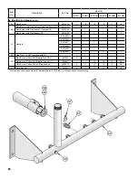
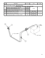
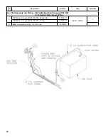
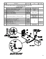
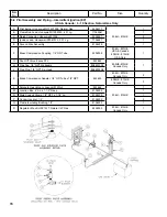
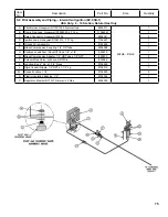
7. Trim and Miscellaneous Controls
A
Limit, 140-220°F, Honeywell
L4080D1218 (EI & Standing Pilot);
L4080B1212 (EP)
80160251
80160474
---
1
1
1
1
1
Immersion Well, ¾” NPT x 1½” Insul. Depth
80160426
1
1
1
1
1
1
Hydrostat 3200 with Sensor (805)
104873-01
1
---
---
---
---
---
LWCO Well for Hydrostat 3200 (if used)
105203-01
1
---
---
---
---
---
B
Limit, Manual Reset, Honeywell L4006E1133
80160703
1
1
1
1
1
1
B1
Immersion Well, ¾” NPT x 3” Insul. Depth
80160452
1
1
1
1
1
1
C
Temperature - Pressure Gauge
100282-01
1
1
1
1
1
1
C1
Nipple, 2 NPT x 10” w/Gauge Tapping
8061601
1
1
1
1
1
1
D
Safety Relief Valve, ¾ NPT, 50 psi
81660302
1
1
1
1
1
1
D1
Nipple, ¾ NPT x 3½”
806600038
1
1
1
1
1
1
E
Drain Valve, ¾ NPT, Conbraco 35-302-03
806603061
1
1
1
1
1
1
E1
Nipple, ¾ NPT x 3½”
806600038
1
1
1
1
1
1
E2
Coupling, ¾ NPT
806602561
1
1
1
1
1
1
F
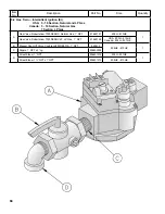
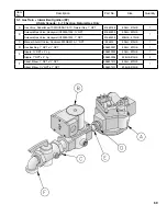
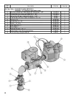
Blocked Vent Switch Replacement Assembly
6016058
1
1
1
1
1
1
G
Flame Roll-out Switch
80160044
1
1
1
1
1
1
G1
Flame Roll-out Switch Mounting Bracket
7181612
1
1
1
1
1
1
H
Junction Box
8136010
1
1
1
1
1
1
J
Control Center, Honeywell R8285D500
(Intermittent Circulation builds)
80160155U
---
1
1
1
1
1
K
Transformer, 50VA (Continuous Circulation builds)
80160249
---
1
1
1
1
1
L
Ignition Module, Honeywell S8610M3009
100958-01
1
1
1
1
1
1
M
Vestibule Wiring Harness, Complete with Vent Damper
Bypass Plug (EI and Standing Pilot) (Not Depicted)
81316010
---
1
1
---
---
---
81316011
---
---
---
1
1
1
N
J-Box to 3200 and Auxiliary Limit Wiring Harness
(not depicted)
81316017
1
---
---
---
---
---
Содержание 805H
Страница 13: ...13 Figure 6 Flame Roll out Switch Installation Figure 7 Burner Burner Access Panel Installation...
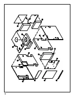
Страница 15: ...15 Figure 8 Jacket Assembly...
Страница 16: ...16 Figure 9 EP Control Installation...
Страница 18: ...18 Figure 10 Schematic Gas Piping 24V Standing Pilot 806H 807HE...
Страница 19: ...19 Figure 11 Main Gas Piping Intermittent Ignition EI...
Страница 20: ...20 Figure 12 Schematic Pilot Piping Honeywell EI USA...
Страница 21: ...21 Figure 13 Schematic Pilot Piping Honeywell EI Canada Natural Gas 805H 810HE LP Gas 806H 807HE...
Страница 22: ...22 Figure 14 Schematic Gas Piping EP Control System Natural Gas Only 806H 810HE...
Страница 23: ...23 Figure 15 Schematic Gas Piping EP CSD 1 Control System 808HE 810HE...
Страница 36: ...36 Figure 27 Wiring Diagram Standing Pilot 24V Continuous Circulation 806H 807HE...
Страница 37: ...37 Figure 28 Wiring Diagram Standing Pilot 24V Intermittent Circulation 806H 807HE...
Страница 39: ...39 Figure 29 Wiring Diagram Honeywell EI USA Canada 805 Only with Hydrostat 3200 Control...
Страница 40: ...40 Figure 30 Wiring Diagram Honeywell EI USA Continuous Circulation 806 810...
Страница 41: ...41 Figure 31 Wiring Diagram Honeywell EI USA Intermittent Circulation 806 810...
Страница 42: ...42 Figure 32 Wiring Diagram Honeywell EI Canada Continuous Circulation Natural 806H 810HE LP 806H 807HE...
Страница 43: ...43 Figure 33 Wiring Diagram Honeywell EI Canada Intermittent Circulation Natural 806H 810HE LP 806H 807HE...
Страница 50: ...50 Figure 40 Lighting Instructions 24V Standing Pilot...
Страница 51: ...51 Figure 41 Operating Instructions EI...
Страница 52: ...52 Figure 42 Operating Instructions EP...
Страница 61: ...61 Honeywell EI Trouble Shooting Guide...
Страница 76: ...76...
Страница 78: ...78...
Страница 82: ...82...
Страница 83: ...83...
Страница 84: ...84...