


25
D.
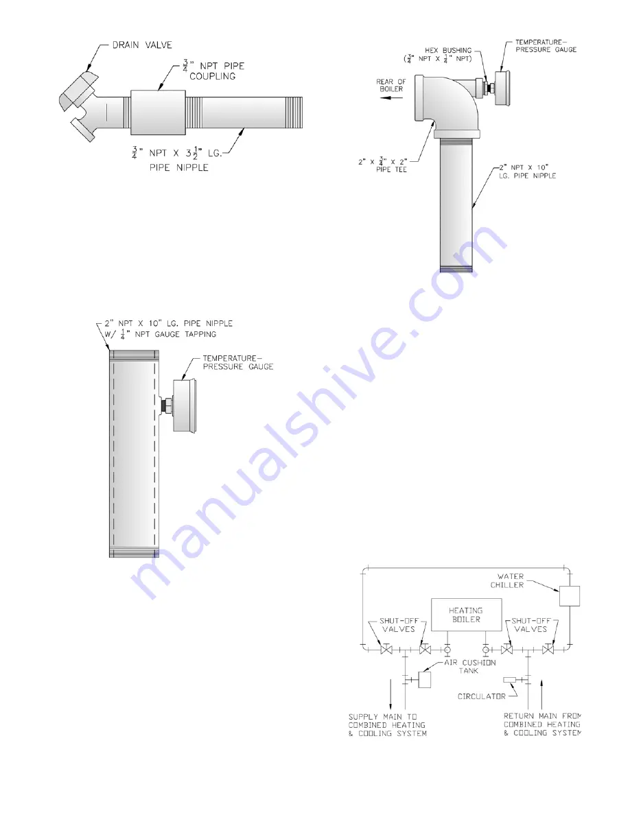
Install Drain Valve
in rear of Left End Section,
Tapping “G”. See Figure 17. Components are located
in Water Trim Carton.
E.
Install Temperature-Pressure Gauge.
Components
are located in Water Trim Carton.
1. Standard Temperature - Pressure Gauge Piping. See
Figure 18.
Figure 17: Drain Piping Installation
Figure 20: Recommended Piping for Combination
Heating & Cooling (Refrigeration) System
a. Install 2” NPT x 10” lg. nipple with gauge
tapping into Supply Tapping “A”. See Figure 3.
Gauge tapping should face forward.
b. Insert Temperature-Pressure Gauge. Tighten
by applying pressure to square shank on back
of gauge. DO NOT APPLY PRESSURE ON
GAUGE CASE since this may ruin gauge
calibration.
2. Alternate Temperature-Pressure Gauge Piping. See
Figure 19.
a. Install 2 NPT x 10” Nipple into Supply Tapping
“A”. See Figure 3.
Figure 18: Temperature-Pressure Gauge
Installation
Figure 19: Alternate Temperature-Pressure Gauge
Installation
b. Install 2 NPT x ¾ NPT x 2 NPT Tee (provided)
or 2 NPT x 2 NPT x ¾ NPT Tee (installer
furnished). ¾ NPT leg should face forward.
c. Install ¾ NPT x ¼ NPT Bushing.
d. Insert Temperature-Pressure Gauge. Tighten
by applying pressure to square shank on back
of gauge. DO NOT APPLY PRESSURE ON
GAUGE CASE since this may ruin gauge
calibration.
F.
Connect system supply and return piping
to boiler.
See Figure 21. Also, consult I=B=R Installation
and Piping Guide No. 250. Maintain minimum ½
inch clearance from hot water piping to combustible
materials.
1. If boiler is used in connection with refrigeration
systems, boiler must be installed with chilled
medium piped in parallel with heating boiler using
appropriate valves to prevent chilled medium from
Содержание 805H
Страница 13: ...13 Figure 6 Flame Roll out Switch Installation Figure 7 Burner Burner Access Panel Installation...
Страница 15: ...15 Figure 8 Jacket Assembly...
Страница 16: ...16 Figure 9 EP Control Installation...
Страница 18: ...18 Figure 10 Schematic Gas Piping 24V Standing Pilot 806H 807HE...
Страница 19: ...19 Figure 11 Main Gas Piping Intermittent Ignition EI...
Страница 20: ...20 Figure 12 Schematic Pilot Piping Honeywell EI USA...
Страница 21: ...21 Figure 13 Schematic Pilot Piping Honeywell EI Canada Natural Gas 805H 810HE LP Gas 806H 807HE...
Страница 22: ...22 Figure 14 Schematic Gas Piping EP Control System Natural Gas Only 806H 810HE...
Страница 23: ...23 Figure 15 Schematic Gas Piping EP CSD 1 Control System 808HE 810HE...
Страница 36: ...36 Figure 27 Wiring Diagram Standing Pilot 24V Continuous Circulation 806H 807HE...
Страница 37: ...37 Figure 28 Wiring Diagram Standing Pilot 24V Intermittent Circulation 806H 807HE...
Страница 39: ...39 Figure 29 Wiring Diagram Honeywell EI USA Canada 805 Only with Hydrostat 3200 Control...
Страница 40: ...40 Figure 30 Wiring Diagram Honeywell EI USA Continuous Circulation 806 810...
Страница 41: ...41 Figure 31 Wiring Diagram Honeywell EI USA Intermittent Circulation 806 810...
Страница 42: ...42 Figure 32 Wiring Diagram Honeywell EI Canada Continuous Circulation Natural 806H 810HE LP 806H 807HE...
Страница 43: ...43 Figure 33 Wiring Diagram Honeywell EI Canada Intermittent Circulation Natural 806H 810HE LP 806H 807HE...
Страница 50: ...50 Figure 40 Lighting Instructions 24V Standing Pilot...
Страница 51: ...51 Figure 41 Operating Instructions EI...
Страница 52: ...52 Figure 42 Operating Instructions EP...
Страница 61: ...61 Honeywell EI Trouble Shooting Guide...
Страница 76: ...76...
Страница 78: ...78...
Страница 82: ...82...
Страница 83: ...83...
Страница 84: ...84...