


26
entering boiler. See Figure 20. Also, consult I=B=R
Installation and Piping Guide No. 250.
2. If boiler is connected to heating coils located in
air handling units where they may be exposed to
refrigerated air, boiler piping must be equipped with
flow control valves to prevent gravity circulation of
boiler water during cooling system operation.
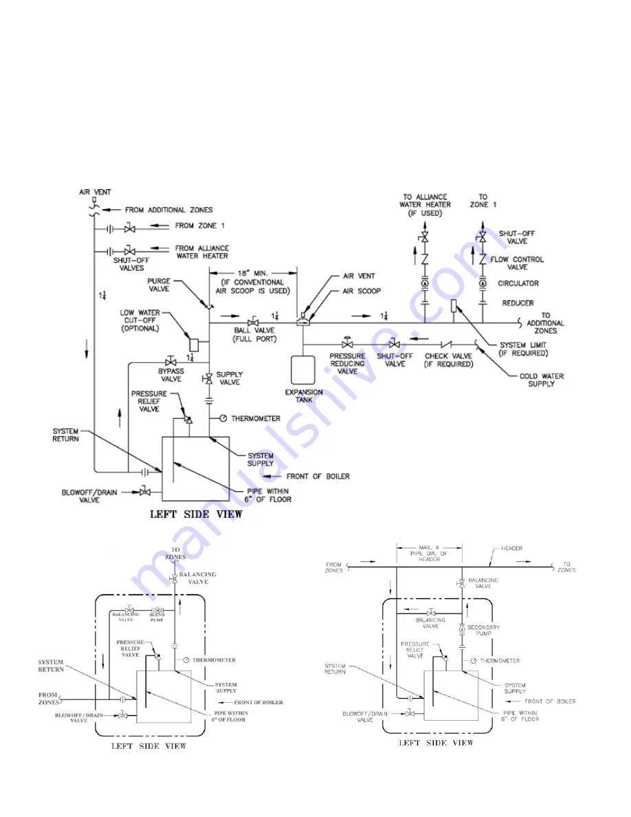
3. The piping diagrams shown (Figure 21, Detail “A”
and Detail “B”) are recommended for optimum
operation and long term reliability.
Burnham Commercial recommends maintaining
temperature differential (drop) across the system
at 40°F or less, and return water temperature at
minimum of 135°F.
Continued boiler operation for prolonged periods of
time under conditions when temperature differential
across the system exceeds 40°F and/or return water
temperature stays below 135°F, may result in
premature boiler failure due to flue gas condensation
and/or thermal shock.
Pump flow rates and minimum boiler supply and
return pipe sizes are shown in Table 4.
Figure 21: Recommended Boiler Piping for Circulator Zoned Heating Systems
Detail “A”: Blend Pump Piping
Detail “B”: Primary/Secondary Piping
with By-Pass
Содержание 805H
Страница 13: ...13 Figure 6 Flame Roll out Switch Installation Figure 7 Burner Burner Access Panel Installation...
Страница 15: ...15 Figure 8 Jacket Assembly...
Страница 16: ...16 Figure 9 EP Control Installation...
Страница 18: ...18 Figure 10 Schematic Gas Piping 24V Standing Pilot 806H 807HE...
Страница 19: ...19 Figure 11 Main Gas Piping Intermittent Ignition EI...
Страница 20: ...20 Figure 12 Schematic Pilot Piping Honeywell EI USA...
Страница 21: ...21 Figure 13 Schematic Pilot Piping Honeywell EI Canada Natural Gas 805H 810HE LP Gas 806H 807HE...
Страница 22: ...22 Figure 14 Schematic Gas Piping EP Control System Natural Gas Only 806H 810HE...
Страница 23: ...23 Figure 15 Schematic Gas Piping EP CSD 1 Control System 808HE 810HE...
Страница 36: ...36 Figure 27 Wiring Diagram Standing Pilot 24V Continuous Circulation 806H 807HE...
Страница 37: ...37 Figure 28 Wiring Diagram Standing Pilot 24V Intermittent Circulation 806H 807HE...
Страница 39: ...39 Figure 29 Wiring Diagram Honeywell EI USA Canada 805 Only with Hydrostat 3200 Control...
Страница 40: ...40 Figure 30 Wiring Diagram Honeywell EI USA Continuous Circulation 806 810...
Страница 41: ...41 Figure 31 Wiring Diagram Honeywell EI USA Intermittent Circulation 806 810...
Страница 42: ...42 Figure 32 Wiring Diagram Honeywell EI Canada Continuous Circulation Natural 806H 810HE LP 806H 807HE...
Страница 43: ...43 Figure 33 Wiring Diagram Honeywell EI Canada Intermittent Circulation Natural 806H 810HE LP 806H 807HE...
Страница 50: ...50 Figure 40 Lighting Instructions 24V Standing Pilot...
Страница 51: ...51 Figure 41 Operating Instructions EI...
Страница 52: ...52 Figure 42 Operating Instructions EP...
Страница 61: ...61 Honeywell EI Trouble Shooting Guide...
Страница 76: ...76...
Страница 78: ...78...
Страница 82: ...82...
Страница 83: ...83...
Страница 84: ...84...