


30
A.
Install vent system
in accordance with local building
codes; or local authority having jurisdiction; or
National Fuel Gas Code
, ANSI Z223.1/NFPA 54, Part
7, Venting of Equipment and/or CAN/CSA B149.1,
Venting Systems and Air Supply for Appliances. Install
any of the following for this Series 8HE Category I,
draft hood equipped appliance:
1. Type B or Type L gas vent. Install in accordance
with listing and manufacturer’s instructions.
2. Masonry or metal chimney. Build and install in
accordance with local building codes; or local
authority having jurisdiction; or
Standard for
Chimneys, Fireplaces, Vents, and Solid Fuel
Burning Appliances,
ANSI/NFPA 211 and/or
National Building Code of Canada
.
Masonry chimney must be lined with approved
clay flue lining or listed chimney lining system
except as provided in ANSI Z223.1/NFPA 54,
Paragraph 7.5.4(a):
Exception: Where permitted by
the authority having jurisdiction, existing chimneys
shall be permitted to have their use continued when
an appliance is replaced by an appliance of similar
type, input rating, and efficiency
.
3. Single wall metal vent. Allowed by ANSI Z223.1/
NFPA 54 under very restrictive conditions.
B.
Inspect chimney
and remove any obstructions or
restrictions. Clean chimney if previously used for solid
or liquid fuel-burning appliances or fireplaces.
Inspect existing chimney before installing boiler.
Failure to clean or replace perforated pipe or tile
lining will cause severe injury or death.
C.
Install Draft Hood
on canopy outlet. Maintain height
from Jacket Top Panel to Draft Hood skirt as shown
in Figure 1. DO NOT ALTER, CUT, OR MODIFY
DRAFT HOOD.
Do not alter boiler draft hood or place any
obstruction or non-approved damper in the
breeching or vent system. Flue gas spillage can
occur. Unsafe boiler operation will occur.
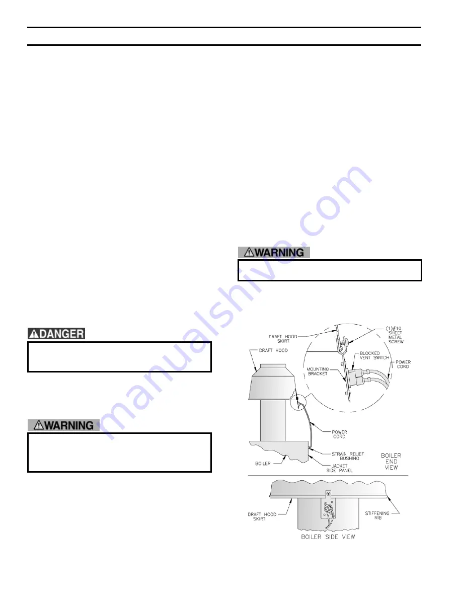
D.
Install Blocked Vent Switch.
The Blocked Vent
Switch Assembly consists of a strain relief bushing,
power cord, and switch attached to mounting bracket.
On Packaged boilers, the assembly is shipped attached
to top of boiler. On Knocked Down boilers, the
assembly is located in Combination Boiler Parts and
Control Carton.
1. Uncoil power cord.
2. Position mounting bracket onto lower edge of Draft
Hood skirt. Locate center tooth (with #10 sheet
metal screw) on outside and other two teeth inside
Draft Hood skirt. See Figure 23.
3. Slide mounting bracket tight against lower edge of
Draft Hood skirt. Position #10 sheet metal screw
above skirt’s stiffening rib.
4. Secure bracket in position by tightening #10 sheet
metal screw against outer surface of Draft Hood
skirt.
5. Insert excess power cord through Jacket Right Side
Panel hole. Remove slack.
6. Position strain relief bushing around power cord.
Pinch bushing’s two halves together and snap back
into hole in Jacket Right Side Panel.
7. Verify power cord, mounting bracket, and Blocked
Vent Switch are secure and located as shown in
Figure 23.
Do not operate boiler without Blocked Vent Switch
Properly installed.
VI. Venting
Figure 23: Blocked Vent Switch Installation
Содержание 805H
Страница 13: ...13 Figure 6 Flame Roll out Switch Installation Figure 7 Burner Burner Access Panel Installation...
Страница 15: ...15 Figure 8 Jacket Assembly...
Страница 16: ...16 Figure 9 EP Control Installation...
Страница 18: ...18 Figure 10 Schematic Gas Piping 24V Standing Pilot 806H 807HE...
Страница 19: ...19 Figure 11 Main Gas Piping Intermittent Ignition EI...
Страница 20: ...20 Figure 12 Schematic Pilot Piping Honeywell EI USA...
Страница 21: ...21 Figure 13 Schematic Pilot Piping Honeywell EI Canada Natural Gas 805H 810HE LP Gas 806H 807HE...
Страница 22: ...22 Figure 14 Schematic Gas Piping EP Control System Natural Gas Only 806H 810HE...
Страница 23: ...23 Figure 15 Schematic Gas Piping EP CSD 1 Control System 808HE 810HE...
Страница 36: ...36 Figure 27 Wiring Diagram Standing Pilot 24V Continuous Circulation 806H 807HE...
Страница 37: ...37 Figure 28 Wiring Diagram Standing Pilot 24V Intermittent Circulation 806H 807HE...
Страница 39: ...39 Figure 29 Wiring Diagram Honeywell EI USA Canada 805 Only with Hydrostat 3200 Control...
Страница 40: ...40 Figure 30 Wiring Diagram Honeywell EI USA Continuous Circulation 806 810...
Страница 41: ...41 Figure 31 Wiring Diagram Honeywell EI USA Intermittent Circulation 806 810...
Страница 42: ...42 Figure 32 Wiring Diagram Honeywell EI Canada Continuous Circulation Natural 806H 810HE LP 806H 807HE...
Страница 43: ...43 Figure 33 Wiring Diagram Honeywell EI Canada Intermittent Circulation Natural 806H 810HE LP 806H 807HE...
Страница 50: ...50 Figure 40 Lighting Instructions 24V Standing Pilot...
Страница 51: ...51 Figure 41 Operating Instructions EI...
Страница 52: ...52 Figure 42 Operating Instructions EP...
Страница 61: ...61 Honeywell EI Trouble Shooting Guide...
Страница 76: ...76...
Страница 78: ...78...
Страница 82: ...82...
Страница 83: ...83...
Страница 84: ...84...