


56
N.
Adjust gas input rate to boiler.
LP/Propane.
1. Set thermostat to highest setting.
2. Adjust tank regulator for gas valve inlet pressure of
13.5 inches w.c. or less.
3. Gas valve has step opening regulator which initially
opens to 1.4 or 2.5 inch w.c. and steps to full
pressure after approximately 30 seconds. Check
manifold pressure after step has occurred. Adjust gas
valve pressure regulator as necessary for 10.0 inches
w.c. (turn adjustment screw counterclockwise to
decrease manifold pressure, or clockwise to increase
manifold pressure). If 10.0 inches w.c. can not be
attained, check gas valve inlet pressure. If less than
11.0 inches w.c., contact gas supplier for assistance.
O.
Clean Heating System
Oil, grease, and other foreign materials which
accumulate in new hot water boilers and a new or
reworked system should be boiled out, and then
thoroughly flushed. A qualified water treatment
chemical specialist should be consulted for
recommendations regarding appropriate chemical
compounds and concentrations which are compatible
with local environmental regulations.
P.
Check Damper Operation
- If boiler is equipped with
vent damper, vent damper must be in open position
when boiler main burners are operating. Start boiler,
refer to instructions on damper to determine if damper
is in full open position.
Q.
Install Front Removable Panel.
1. Engage top flange (longer of 2 flanges) behind
Upper Front Panel.
2. Swing lower portion of door toward boiler.
3. Lower door to engage bottom flange behind Lower
Front Tie Bar.
R.
Combustion Chamber Burn-Off
1. The mineral wool combustion chamber panels
contain a cornstarch based binder that must be
burned out at installation to prevent odors during
subsequent boiler operation.
2. Ventilate the boiler room, set the high limit to its
maximum setting, set the thermostat to call for heat.
3. Allow the boiler to fire for at least an hour or until
the odor from the cornstarch has dissipated.
4. Return the high limit and thermostat to their desired
settings.
S.
Review User’s Information Manual
and system
operation with owner or operator.
Model 805 Only:
IMPORTANT
This boiler is equipped with a feature that saves energy by reducing the boiler water temperature
as the heating load decreases. This feature is equipped with an override which is provided
primarily to permit the use of an external energy management system that serves the same
function. THIS OVERRIDE MUST NOT BE USED UNLESS AT LEAST ONE OF THE
FOLLOWING CONDITIONS IS TRUE:
• An external energy management system is installed that reduces the boiler
water temperature as the heating load decreases.
• This boiler is not used for any space heating.
• This boiler is part of a modular or multiple boiler system having a total input
of 300,000 BTU/hr or greater.
• This boiler is equipped with a tankless coil.
Содержание 805H
Страница 13: ...13 Figure 6 Flame Roll out Switch Installation Figure 7 Burner Burner Access Panel Installation...
Страница 15: ...15 Figure 8 Jacket Assembly...
Страница 16: ...16 Figure 9 EP Control Installation...
Страница 18: ...18 Figure 10 Schematic Gas Piping 24V Standing Pilot 806H 807HE...
Страница 19: ...19 Figure 11 Main Gas Piping Intermittent Ignition EI...
Страница 20: ...20 Figure 12 Schematic Pilot Piping Honeywell EI USA...
Страница 21: ...21 Figure 13 Schematic Pilot Piping Honeywell EI Canada Natural Gas 805H 810HE LP Gas 806H 807HE...
Страница 22: ...22 Figure 14 Schematic Gas Piping EP Control System Natural Gas Only 806H 810HE...
Страница 23: ...23 Figure 15 Schematic Gas Piping EP CSD 1 Control System 808HE 810HE...
Страница 36: ...36 Figure 27 Wiring Diagram Standing Pilot 24V Continuous Circulation 806H 807HE...
Страница 37: ...37 Figure 28 Wiring Diagram Standing Pilot 24V Intermittent Circulation 806H 807HE...
Страница 39: ...39 Figure 29 Wiring Diagram Honeywell EI USA Canada 805 Only with Hydrostat 3200 Control...
Страница 40: ...40 Figure 30 Wiring Diagram Honeywell EI USA Continuous Circulation 806 810...
Страница 41: ...41 Figure 31 Wiring Diagram Honeywell EI USA Intermittent Circulation 806 810...
Страница 42: ...42 Figure 32 Wiring Diagram Honeywell EI Canada Continuous Circulation Natural 806H 810HE LP 806H 807HE...
Страница 43: ...43 Figure 33 Wiring Diagram Honeywell EI Canada Intermittent Circulation Natural 806H 810HE LP 806H 807HE...
Страница 50: ...50 Figure 40 Lighting Instructions 24V Standing Pilot...
Страница 51: ...51 Figure 41 Operating Instructions EI...
Страница 52: ...52 Figure 42 Operating Instructions EP...
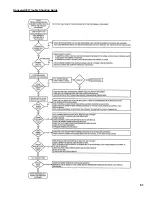
Страница 61: ...61 Honeywell EI Trouble Shooting Guide...
Страница 76: ...76...
Страница 78: ...78...
Страница 82: ...82...
Страница 83: ...83...
Страница 84: ...84...