
CCD-Premium
Operating manual
page 7 /24
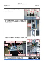
At the power supply are two sockets, which are switched on and off together with the spindle mo-
tor. These sockets can be used e.g. for the vacuum cleaner or a magnetic valve for cooling
device. Each socket may not take more than 5 A (1150 W at 230 V AC).
For the connection of safety switches (e.g. hood switches) a shielded cable should be used, it
must be kept as short as possible. This cable - just like all remaining connection/feeder cables
between Controller and CCD - should not be laid parallel to power cables in order to prevent in-
ductive or capacitive linking of high-energy transients and thus possible over voltage damage in
the Controller.
Not avoidable crossings with power cables must be right-angle implemented to keep couple-strain
as short as possible.
If in the proximity of the machines high inductive loads are operated like e.g. strong electric mo-
tors, exhaust fans, contactors etc., the employment of an opto coupler can be necessary for the
connection of the hood contact/safety switch.
All damages due to over voltage, overheating, humidity, dust, corrosion or inappropriate connec-
tion of external or electronic devices are excluded of the guarantee. These repairs will be
charged.
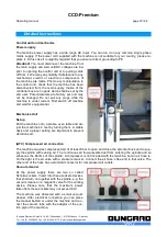
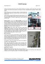
Maintenance
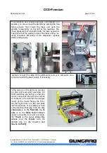
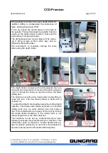
It is important that you regularly remove all dust and shavings from the machine. To clean and lub-
ricate the steel shafts, especially those below the aluminium extrusions on the X-axis, use a cloth
and some acid-free machine oil. On each end of the linear bearing housings, there are lubricating
felt stripes. Regularly apply some oil to them. If the machine will not be used for a longer period or
prior to transport, all steel shafts should be well lubricated.
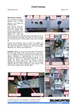
The ball gear drive of the z-axis needs to get cleaned from chips and dust regularly and greased
with a suitable grease.
The drive belts must also be kept clean from dust and shavings but must not not be lubricated.
The belts are subject to wear. If they show damages like lateral fray-out or deformed teeth they
should be replaced.
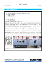
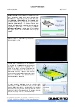
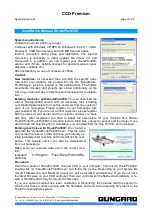
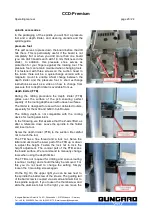
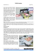
Tools
Only tools with ring (collar) should be used. The distance flange determines the spindle elevation
over the table. The distance from the top edge of the ring to the tool tip is 21 mm. It is mounted to
the spindle at the factory in a way that a drill with ring is 0.5 mm over the machine table when the
Z axis is completely down. You should not change this setting. Otherwise the mechanical position
of the Z axis will be different from the one assumed by the driver software. Damage to the ma-
chine table may then result.
Documentation
Our distributor / reseller in your country is encouraged and in charge of translating the German
and / or English manual coming with the machine into your native language. A declaration of EU
conformity is appending.
Bungard Elektronik GmbH & Co. KG, Rilkestraße 1, 51570 Windeck – Germany
Tel.: +49 (0) 2292/5036, Fax: +49 (0) 2292/6175, E-mail: [email protected]


