
CCD-Premium
Operating manual
page 19 /24
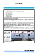
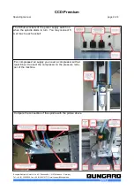
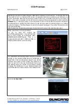
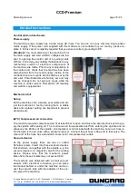
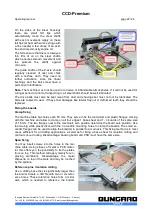
Mounting the spindle
The machine is normally
supplied with mounted
spindle. If not, follow the
following steps:
Open with an Allen key
the two mounting screws.
Insert the spindle from
the top until it rests on the
spindle holder. Rotate the
spindle so that the
junction box does not interfere with moving parts of the Z-
axis and tighten the fixing screws again. Connect the cable
to the 3-pin connector to the socket on top of the controller
bar.
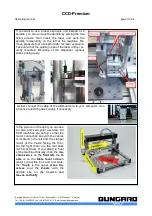
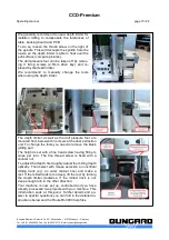
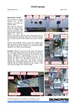
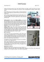
Connect the pressure hose to open the spindle and
pressure hose for sealing air as shown in the picture. Make
sure that there always is a testpin or a drill in the spindle.
Otherwise, the chuck may be damaged.
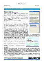
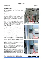
I
mportant
: Please only use tools with rings. The distance
from the upper edge of the ring to the tip of the tool is 21
mm. The distance between the drill tip and the table top is
already calibrated to approximately 0.5 mm. In the
software, the distance can be changed, but please: do not
change the value if not absolutely needed. If you do
change the value, please be very careful, because
otherwise the mechanical position of the Z-axis no longer
matches with the position adopted by the program. This
could cause damage to the machine table.
Bungard Elektronik GmbH & Co. KG, Rilkestraße 1, 51570 Windeck – Germany
Tel.: +49 (0) 2292/5036, Fax: +49 (0) 2292/6175, E-mail: [email protected]


