CCD-Premium
Operating manual
page 21 /24
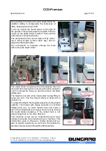
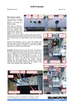
spindle up and down about 10 mm. This way the spindle is not rigidly coupled to the Z-axis, but is able
to follow the contour of the surface in the range of 10 mm. This guarantees a perfectly uniform cutting
depth.
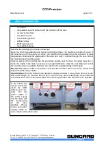
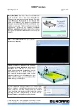
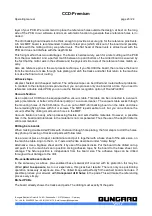
When drilling and cut-out-routing (countour routing) spindle and
Z-axis should always be connected firmly over the alu bar and
thumbscrew.
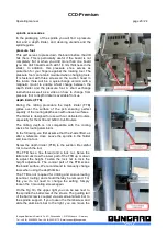
When isolation milling the FTB follows the board surface. To do
this, set a cutting depth of about 0.1 to 0.5 mm in the tool menu
of RoutePro3000, to ensure the depth limiter really touches the
board surface.
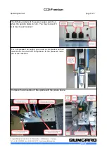
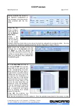
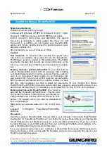
Setting option 1:
Go to the tab
Manual Mode
and move the
axis using the arrow keys. The actual cutting depth is obtained
from the difference of the height of the shoe and the tool tip.
Therefore gently turn the screw part of the FTB with the spindle
running until the tool just touches the board. Always make sure
that first the shoe and then the cutter tip touches the surface.
Warning
: Do not reach into the rotating tool!
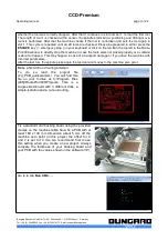
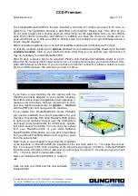
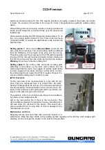
Setting option 2:
Go to Run CNC and mark a cutting path,
preferably a non-critical, eg the later outer contour. Set the
cutting depth first by vision (we suggest to set the depth rather
too high instead of too deep) and test cut this track. Control
the milling depth and adjust the FTB if needed. Repeat the
process until the milling depth / width is correct.
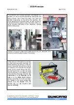
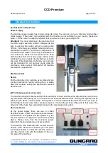
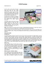
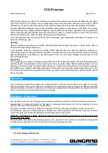
(ATC) Tool slots
On the right side of the machine there is a bar with 30 tool
slots. They are numbered from 0 to 29 (ATC/XL: 25 slots).
Number 0 always takes the test pin. The drill and router bits go
into the remaining round aluminium slots. A tool can move ver-
tically in this container and a spring will shift it up until the tool
ring is on the same height as the tool slot.
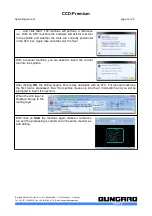
The positions of the tool containers are known to the software
by entries to the configuration file.
Left to the tool position No. 0 there is the tool sensor. The
driver software operates the machine in a way, that after each
drill was used it is checked in this sensor. This sensor also
acts as a detector for too long drills, so that no damage to the
machine bed can occur.
Maintenance and Care
Regularly remove dust and chips with a vacuum cleaner or a
small brush. Wipe the steel shafts of the guiding profiles regularly with a lint-free cloth soaked with
acid-free oil. Do not forget the shafts on the bottom of the profiles!
Bungard Elektronik GmbH & Co. KG, Rilkestraße 1, 51570 Windeck – Germany
Tel.: +49 (0) 2292/5036, Fax: +49 (0) 2292/6175, E-mail: [email protected]