background image

CCD-Premium

Operating manual

page 22 /24

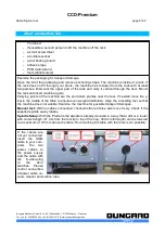
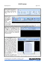
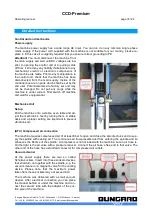
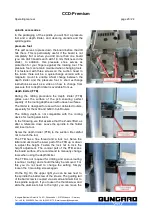
On   the   sides   of   the   linear   housings
there   are   small   felt   tips   which
automatically   clean   the   steel   shafts
with each movement. Apply on these
felt tips (at best with some syringe with
a fine needle) a few drops of an acid-
free and low-viscosity engine oil.
The felts ensure that there is always a
thin   film   of   oil   on   the   steel   shafts,
which ensures smooth movement and
the   protects   the   shafts   against
corrosion. 

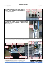
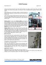
The guide shafts of the Z-axis should
regularly   cleaned   of   dust   and   chips
with   a   lint-free   cloth.   They  need   no
further   lubrication,   since   the   linear
bushings   and   the   ball   screw   have   a
permanent lubrification.

Note

: The machine must not be used in corrosive or inflammable atmospheres. If it will not be used for

a longer period or prior to transporting it, all steel shafts should be well lubricated.
The drive belts must also be kept clean from dust and shavings but must not not be lubricated. The
belts are subject to wear. If they show damages like lateral fray-out or deformed teeth they should be
replaced. 

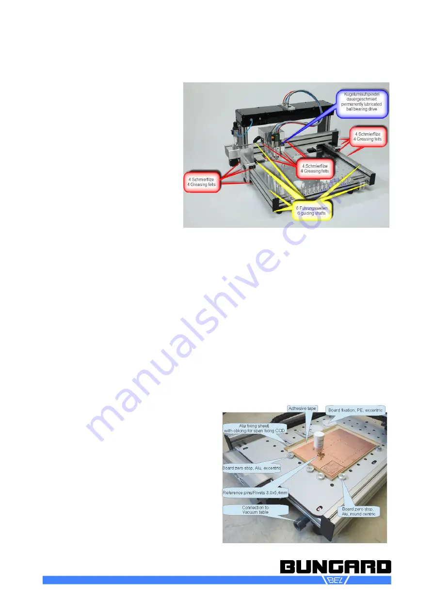
Fixing the boards

Clamp fixing

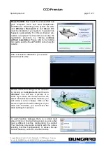
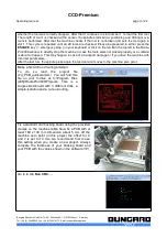
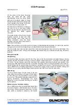
The machine table has holes each 50 mm. They serve to fix the aluminium and plastic flanges coming
with the machine and allow to clamp on all four edges 1 base sheet and 1 - 3 boards of the same size
of 1.5 mm. The two flanges near to the machine's zero position determine the board zero position. Use
the two big white plastic discs with the 3 eccentric mounting holes to clamp the boards. The small ec -
centric flanges can be used to align the board(s) in parallel to a main axis. This fixing method is in most
cases sufficient for all drilling applications, as well as for fixing a base sheet for isolation milling and
contour cut-out routing. Disadvantage: backing board and PCB must have the same size.

Span fixing

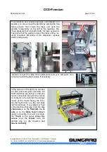
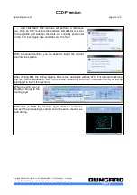
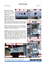
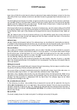
You may insert screws into the holes in the ma-
chine table. Using stripes of metal or PCB mater-
ial, this offers you the possibility to fix the plates
from on top. This method will apply mainly for en-
graving   aluminium.   Disadvantage:   the   metal
stripes lie on top of the plate and may be touched
by the spindle.

Reference pins / Isolation milling

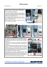
Use a drilling base that is significantly larger than
the board. Create a drill file with two or six refer-
ence holes. These reference holes form a mirror
axis,   which   is   needed   to   reference   the   bottom

Bungard Elektronik GmbH & Co. KG, Rilkestraße 1, 51570 Windeck – Germany

Tel.: +49 (0) 2292/5036, Fax: +49 (0) 2292/6175, E-mail: [email protected]

Содержание CCD/2

Страница 1: ...CCD Premium Operating manual page 1 24 Bungard Elektronik GmbH Co KG Rilkestraße 1 51570 Windeck Germany Tel 49 0 2292 5036 Fax 49 0 2292 6175 E mail support bungard de ...

Страница 2: ...nstruction Set 8 Installation Manual RoutePro3000 16 Detailed Instructions 18 Control unit and mechanics 18 Power supply 18 Mechanics Unit 18 Set up 18 ATC Compressed air connection 18 Vacuum cleaner 18 Mounting the spindle 19 ATC Tool slots 21 Fixing the boards 22 Clamp fixing 22 Span fixing 22 Reference pins Isolation milling 22 Adhesive tape 23 Vacuum fixation 23 Drilling bare boards 23 Pre sen...

Страница 3: ...or smallest tool diameters 300 W spindle stepper motor torque adjustable via software 30 tool boxes for automatic tool change tool length measurement and calibration incl tool break control integral pressure foot and depth limiter system dust extraction with autostart function via software rollrack with transparent 2 doors with security switches Laser head for LDI Standard software supplied with t...

Страница 4: ...is 22 000 mm min 150 mm s Maximum working speed per axis 22 000 mm min 150 mm s individual settings for each tool independent of positioning speed Drill performance 5 s 18 000 holes h 300 holes min bread board Necessary equipment Computer ATC compressed air 6 bar Board fixation Clamp fixing span fixing reference pin system batch processing possible optional vacuum fixation Machine size Working are...

Страница 5: ...ine using the main switch of the control unit In this case wait until the spindle has come to a standstill Protection against contact with moving parts The machine may only be operated in an enclosed protection cover With door switches so that maintenance work can only be done with the machine at stand still Location Put the machine onto a stable even table and adjust the machine s 4 feet by turni...

Страница 6: ...e laser light Note the laser exposure unit may only be operated in a closed rack or hood Please observe the general rules for handling electronic parts especially ESD protection Before touching the laser head perform a potential compensation E g put you both hands on an ESD suitable support before removing the laser from the package You need to do the same before you reassemble the laser from the ...

Страница 7: ...eel shafts especially those below the aluminium extrusions on the X axis use a cloth and some acid free machine oil On each end of the linear bearing housings there are lubricating felt stripes Regularly apply some oil to them If the machine will not be used for a longer period or prior to transport all steel shafts should be well lubricated The ball gear drive of the z axis needs to get cleaned f...

Страница 8: ...nsure even weight distribution Align the 4 levelling feet so that the machine does not wobble Examine the machine for possible transport damages Manual test With no cables connected check whether all three axis move freely Check if the supplied spindle easily rotates Spindle Setup With the Premium the spindle is already mounted in a way that a drill or a router with correct length 21 mm from the t...

Страница 9: ...t max to each socket For compressed air supply you need a compressor with at least 6 bar Connect the compressor to the pressure redu cer of the machine Compare the connection of the spindle with the picture above Bungard Elektronik GmbH Co KG Rilkestraße 1 51570 Windeck Germany Tel 49 0 2292 5036 Fax 49 0 2292 6175 E mail support bungard de ...

Страница 10: ...ower supply if necessary In the picture on the right you can see an axis and zero point overview All CCD machines are set up so that the motor connection box with the cables is located on the left and the stepper motor of the Y axis facing the front On the right there are the tool slots ATC machines If you stand in front of the machine that way then the ma chine zero is on the front left the X axi...

Страница 11: ...ease check the settings of the machine by clicking on the Options tab and then on machine You will see a picture of a CCD If you hover the mouse over the dif ferent functional areas of the machine you will notice a colour change Click on the areas to open the function dialogue If you drive over the table you can access the table settings for example In each function dialogue there is a small tooth...

Страница 12: ...e Pro3000 Projects Go to tab Run CNC and click on the triangle START The next dia logue asks you to place the tool to the corresponding tool slots Make sure that the tools have a length of 38 mm and the distance between the top of the ring to the tool tip is 21 mm Furthermore a test tool must be in the spindle and the tool slot 0 must be empty Check the correct fitting of the tools in the slots Si...

Страница 13: ...h incorrect parameters After the last tool the spindle picks again the test tool and moves to the machine zero point Make a first drill and routing attempt To do so load the project file ccd_PCB_quickstart xml You will find this file on your C drive at C Program Files x86 RoutePro3000 Projects This is a single sided board with 3 different drills a simple isolation and a cut out routing Fix a stand...

Страница 14: ...le After clicking OK the drilling begins This is fully automatic with an ATC For manual machines the first tool is processed then the machine moves up into the Z limit switch and you will be prompted to insert the next tool When the drill layer is finished change to the routing layer With click on Start the machine again makes a reference run and the processing is carried out in the same manner as...

Страница 15: ...you need to remove the black gliding part The height is set with a fine tread screw having 500 µm slope per turn The fine thread screw is fixed with a counter nut To adjust the depth first roughly adjust the milling depth optically Then select with mouse selection an uncritical milling track e g an outer contour line and make a test If the milled track is too deep lift the tool by turning the dept...

Страница 16: ...ave with him After installation you have to adapt the parameters for your machine from Route Pro2008 into RoutePro3000 correction factors table size values for sensor and tool slots If you want to read the help file prior to installation you can download the help file from our homepage Existing machines with RoutePro3000 We created a separate file UpdateRoutePro3000 exe This file does not contain ...

Страница 17: ...is done If you have a new machine the CD coming with the machine is already adapted to your specific machine No further action beyond registration and activating li censes need to be done Still we recommend to com pare the machine parameters at options machine with the PDF print out coming with the machine If you update from RoutePro2008 to Route Pro3000 you need to establish the correct parameter...

Страница 18: ...d just the machine s 4 feet by turning them A stable desk and a proper setting are important to prevent vibrations etc ATC Compressed air connection The machine requires compressed air of at least 6 bar to open and close the spindle chuck and to sup ply the spindle with sealing air The continuous air flow prevents dust from entering the spindle and so enhances the lifetime of the spindle A compres...

Страница 19: ...he picture Make sure that there always is a testpin or a drill in the spindle Otherwise the chuck may be damaged Important Please only use tools with rings The distance from the upper edge of the ring to the tip of the tool is 21 mm The distance between the drill tip and the table top is already calibrated to approximately 0 5 mm In the software the distance can be changed but please do not change...

Страница 20: ... limiter is designed for use with our delivered routers especially for the G30 and G60 V Cut Routers The milling depth is not compatible with the cooling device for routing aluminium In the following we first assume that the Z axis lifted as after a reference drive Leave the spindle in the holder and insert a tool Screw the depth limiter FTB to the suction Be careful not to touch the tool The FTB ...

Страница 21: ...h first by vision we suggest to set the depth rather too high instead of too deep and test cut this track Control the milling depth and adjust the FTB if needed Repeat the process until the milling depth width is correct ATC Tool slots On the right side of the machine there is a bar with 30 tool slots They are numbered from 0 to 29 ATC XL 25 slots Number 0 always takes the test pin The drill and r...

Страница 22: ...rve to fix the aluminium and plastic flanges coming with the machine and allow to clamp on all four edges 1 base sheet and 1 3 boards of the same size of 1 5 mm The two flanges near to the machine s zero position determine the board zero position Use the two big white plastic discs with the 3 eccentric mounting holes to clamp the boards The small ec centric flanges can be used to align the board s...

Страница 23: ...ugh the mounting holes of the CCD table You can put an MDF drill backing board on the table and close the remaining fixing holes with foil or screws The MDF is permeable to air but you can enhance the vacuum effect by drilling small suction holes in the MDF Vacuum fixation is handy when processing flexible and semi flexible materials However a possible bow in the board and tolerances in the materi...

Страница 24: ...ng you can work with the depth limiter However in this case the cooling is less efficient because the milling tool is almost completely enclosed Another trick is to bend the engraving plate a bit so the the sides of the plate point upward Now when you span down both sides the engraving plate will lie flat on the base Guarantee Prior to delivery all machines undergo an operational test on function ...

Отзывы: