
CCD-Premium
Operating manual
page 13 /24
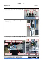
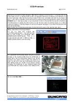
whether the tool was correctly dropped. After that it continues to slot number 1 to load the first tool.
The length of tool 1 is checked at the sensor, the spindle starts and a positioning and drilling move-
ment is performed. After that the machine checks if the tool is not broken and sets the tool again in
slot 1. This cycle is repeated until all 29 tools are checked. Please be prepared to either press the
ESCAPE
key ( = emergency stop ) on your keyboard or click on the red
X
in the top left in the Route-
Pro3000 window to directly stop the machine in case the tools were not picked properly or a collision
is about to happen. This may happen in case of a transport damage or if you drive the machine with
incorrect parameters.
After the last tool, the spindle picks again the test tool and moves to the machine zero point.
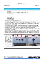
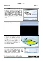
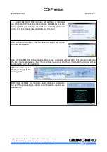
Make a first drill and routing attempt!
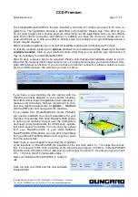
To do so load the project file
ccd_PCB_quickstart.xml. You will find this
file on your C-drive at: C:\Program Files
(x86)\RoutePro3000\Projects. This is a
single sided board with 3 different drills, a
simple isolation and a cut-out-routing.
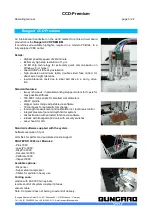
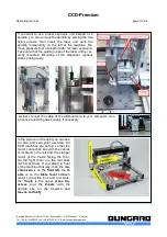
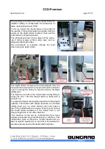
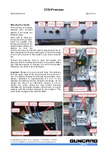
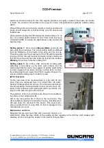
Fix a standard drill backing board using the provided
clamps on the machine table. Now fix a PCB with at
least 160 x 100 mm dimension about 5 mm off the
machine zero point (in this project the offset for X
and Y is set to 10 mm, we recommend first to use
this setting when you create a new project. Always
compare the thickness of your backing board and
your PCB with the values shown in the software !!!l!)
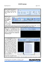
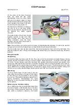
Go to to tab
Run CNC
.....
Bungard Elektronik GmbH & Co. KG, Rilkestraße 1, 51570 Windeck – Germany
Tel.: +49 (0) 2292/5036, Fax: +49 (0) 2292/6175, E-mail: [email protected]


