35
20.5 Application
Notes
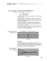
100Hz Notch to reduce mains related interference
The design specification for this would be:
Fc
= 100Hz
Q
= Maximum possible
dB cut= Maximum possible
Using the Fc equation given earlier, and selecting Cf = 220nF gives a value
for Rf = 7.23k ohms.
Using the graph for Rq will indicate that for a maximum value for Q, the
value of Rq should be also be a maximum. In this circuit we can allow Rq to
be infinite, so the design value for Rq would be open circuit, and no resistor
would be fitted in this position.
Using the graph for RdB will indicate that a minimum value for RdB is
required for a maximum value for boost/cut. In this circuit we can set a
minimum value for this of 10k ohms. (Ensure this resistor is fitted in the 'cut'
of 'C' position on the circuit board).
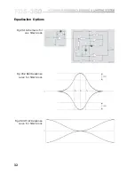
Notch depths of up to 50dB can be achieved, however this depends on the
close matching of the frequency determining components. An example of this
notch circuit is shown below in
Figure 20.6
.
20
50
100
200
500
1k
2k
5k
10k
20k
40k
10dB
Notch Response RQ =
, Rcut = 10k, Fc = 960Hz
Frequency (Hz)
8
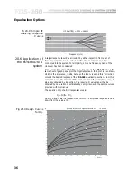
Shelving Filter:
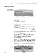
Utilising the parametric section and selecting a very low Q value will
achieve a standard shelving type response filter of their boost or cut. Selecting
a low Fc (such as 30Hz) will give a bass shelving response, and selecting a
high Fc (such as 20kHz) will give a treble shelving response. An example of
these shelving curves is given below in
Figure 20.7
.
Fig 20.7 Sample LF
Shelving Response
Curves
Fig 20.6 Sample Notch
Response Curve
20
50
100
200
500
1k
2k
5k
10k
20k
40k
5dB
LF Shelf RQ = 0, Fc = 35Hz (Response difference due to subsonic filter.)
Frequency (Hz)
Содержание FDS 360
Страница 1: ...1 FDS 360 User Manual...
Страница 51: ...51 User Notes...
Страница 52: ...52 User Notes...
Страница 53: ...53...
Страница 54: ...54 User Notes...

