3 4
20
50
100
200
500
1k
2k
5k
10k
20k
40k
10dB
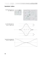
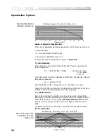
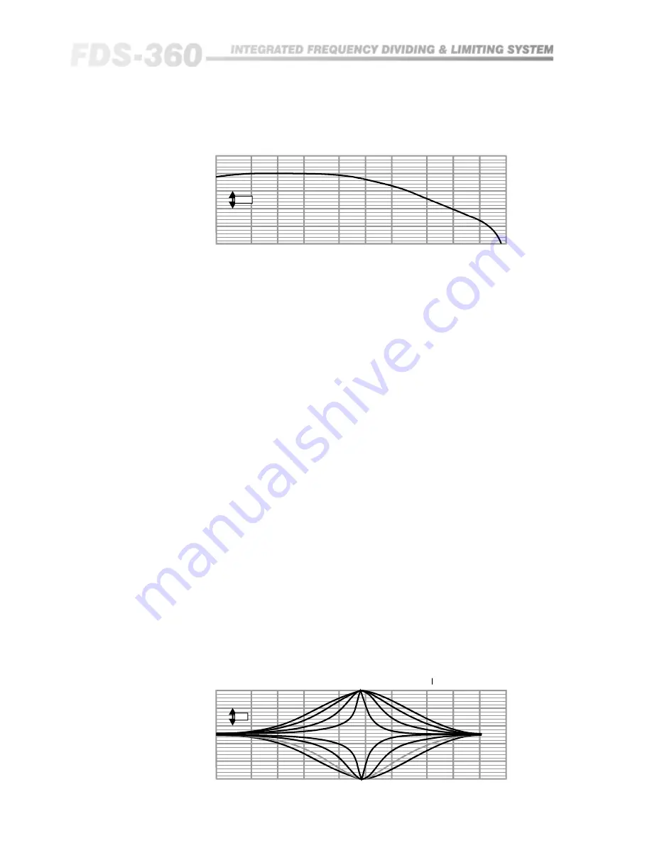
First Order Response Cf = 15nF, Fc (-3dB) = 1kHz
Frequency (Hz)
Section B: Parametric Equaliser Filter.
This is a fully adjustable bell shape equaliser for which control is given over:
•
Centre frequency
•
Q, or the sharpness of the Bell shape
•
The amount in dB of the boost or cut.
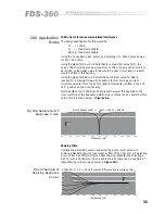
A sample response of this equaliser is shown in
Figure 20.5
:
1. Centre Frequency:
This is set by four components; Rfa, Rfb, Cfa and Cfb, and is given by the
following equation:
Fc = 1/[6.28 (R*fa/b . C*fa/b)],
where R is in ohms,
C is in Farads,
F is in Hz.
For symmetrical and normal responses note that Rfa = Rfb and Cfa = Cfb, and
the equation reduces to:
Fc = 1/(6.28 x Rf x Cf)
Such that for Rfa = Rfb = 10k and Cfa = Cfb = 16nF than Fc = 1kHz.
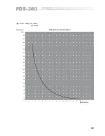
Design limits for Rf should be within the range 2k to 100k ohms. There are no
limits for Cf apart from physical space on the circuit board.
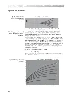
2. Q and dB Boost/Cut:
Both of the parameters Q and dB are set by a single resistor, Rq and RdB
respectively. To some extent they are interactive and it is therefore easiest to
obtain their values from a set of graphs (
See figure 20.10 and 20.11
). These
allow for ranges of Q from 0.2 to 3.0 and for a range of boost/cut of up to
16dB.
For further information on deciding on the values of these filter variables,
refer to section 20.5
.
Fig 20.4 First Order
Sample Response
20
50
100
200
500
1k
2k
5k
10k
20k
40k
5dB
Bell Response RQ values, 0 , 1k , 4k7,
= 12.5dB
Frequency (Hz)
Ω
Ω
8
Fig 20.5 Parametric
Equaliser Sample
Response
Equalisation Options
Содержание FDS 360
Страница 1: ...1 FDS 360 User Manual...
Страница 51: ...51 User Notes...
Страница 52: ...52 User Notes...
Страница 53: ...53...
Страница 54: ...54 User Notes...

